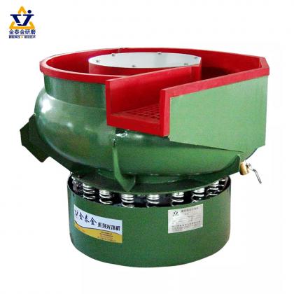
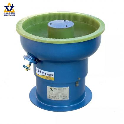
• Save Time and Money with a Tumbling machine
    Save Time and Money with a Tumbling machine June 30, 2022
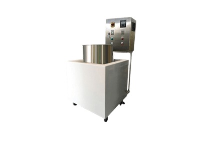
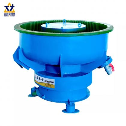
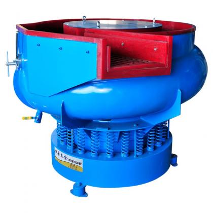
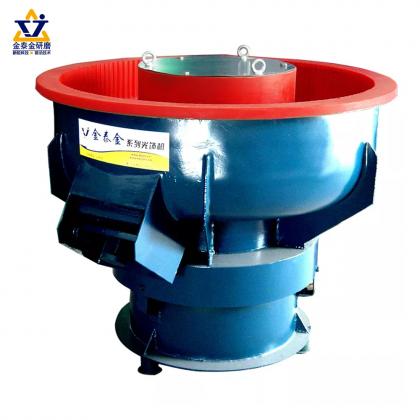
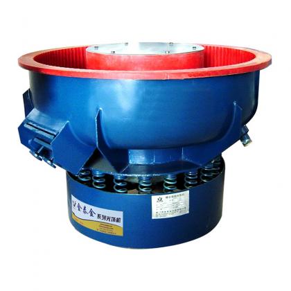
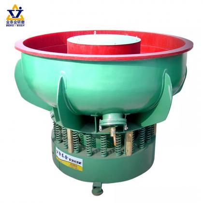
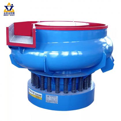
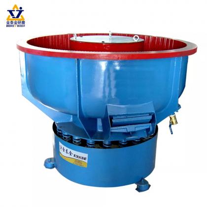
    Save Time, Grit, Polish and Electricity Compare to traditional polishing machine- vibration, our tumbling machine for injection can help the producers to save time and money. Here we have a comparison for your reference: Now, let’s introduce this machine by details: Firstly, the appearance of machine base on the design in year 2018, we made more improved in size, safety protection and operation ease. Secondly, it about the reduce the noise. For vibration, one machine will cause higher than 95 db, when it works. And if more 6 sets machines working together, the decibel will be higher than 130 db, which are very harmful for the operators, But for the tumbling machine, one machine will cause lower than 60 db, and it won’t higher than 85 db, even 18 sets machine working together. Thirdly, this machine controlled by PLC, which make sure the polishing time are same in positive and negative rotation. The surface finished will be more stable. Fourth, the automatic water inlet and outlet system, improve the surface clearness of products, which will be better for painting step, save the paint and increase the spray paint quality. Here we take injection sunglasses as reference: This polishing machine effective for inner groove & model line,saving paint due to the smooth surface finished. There are only 2 step for the whole polishing process: 1.5 hrs for rough polishing and 0.5 hrs for fine polishing. According to all the data, we recommend this tumbling machine for injection products.
    View More
  • Surface finished of electrical heated tube(copper)
    Surface finished of electrical heated tube(copper) January 12, 2022
    We have different kinds of polishing machines. Totally can be divided into two main types: wet polishing and dry polishing. For wet polishing process, the media and paste need to mix with water together inside the machines. Magnetic machine is one of this machine. The electrical heated tube (copper) can be polished in the magnetic machine. In fact, the small metal piece without magnetism can be put inside this machine, such as copper, stainless steel, aluminum, titanium... This is magnetic polishing machine. It has super strong magnetic force to drive the small grinding steel needles to produce effects, such as high suspension flowing vibration and reverse rolling to create friction. Here we take electrical heated tube (copper) as example: Original piece,rough and dirty... After 30 min. polishing in the magnetic machine, the surface finished will be like: For more details, welcome to contact us for polishing process
    View More
  • When Dry Finishing Needs Dust Extraction and Housekeeping Controls
    When Dry Finishing Needs Dust Extraction and Housekeeping Controls August 10, 2026
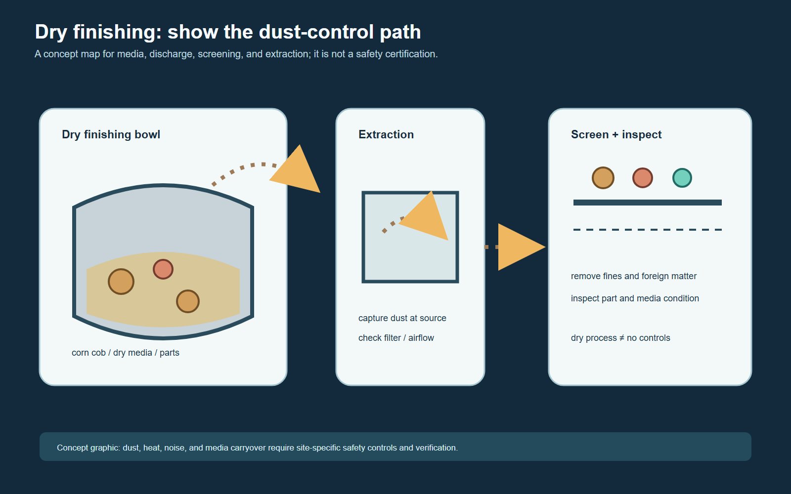
    When Dry Finishing Needs Dust Extraction and Housekeeping Controls Dry mass finishing can generate or release fine particles from media wear, workpiece residue and handling. Whether a process needs local exhaust ventilation, enclosed transfer or additional housekeeping controls must be decided from the actual dust, material safety information, machine arrangement and workplace risk assessment. A finishing-machine setting alone cannot answer that question. Start with the material and dust hazard Identify every material entering the process: workpieces, dry media, additives, coatings and residues. Review the current safety data supplied for each material and determine what dust may be generated during finishing, screening, unloading and cleaning. Do not assume that a dust is harmless because the bulk material appears familiar. Some finely divided materials can create respiratory, fire or deflagration hazards. OSHA notes that combustible dust hazards can occur with materials including metals, plastics, wood and rubber. The exact hazard and required controls depend on the real dust and facility, so testing and competent safety review may be necessary. Look beyond the finishing bowl Dust release can occur at loading, during machine operation, at discharge, through screening, when media is returned and while containers or filters are handled. Walk the complete material route and record visible escape points, settled deposits and tasks that disturb dust. A clean machine exterior does not prove that ducts, ledges or downstream handling points are clean. Conceptual dry-finishing flow: verify the actual capture points, dust properties and safety requirements before specifying extraction equipment. When local exhaust ventilation should be evaluated Local exhaust ventilation is intended to capture an airborne contaminant close to where it is generated. HSE guidance emphasizes that effective LEV depends on suitable hood design, ducts, air movers, air cleaning, commissioning, checking and maintenance. A generic fan or an unverified connection is not evidence of adequate control. Evaluate LEV when dust becomes airborne during normal work, escapes at transfer points, accumulates around the process, or when the material risk assessment calls for engineering control. Capture design must match the source and task without disrupting safe machine operation or spreading contamination to another area. Housekeeping is part of process control A written cleaning routine should identify areas, methods, frequency, responsibility and evidence of completion. Include floors and accessible surfaces as well as beams, cable trays, machine frames, enclosure edges and collection points where dust can settle. Cleaning frequency should be based on observed accumulation and the assessed hazard, not an invented universal interval. Avoid cleaning methods that disperse settled dust into the air. OSHA guidance specifically warns against using compressed air to clear dust surfaces where co...
    View More
  • When Dry Finishing Needs Dust Extraction and Housekeeping Controls
    When Dry Finishing Needs Dust Extraction and Housekeeping Controls August 10, 2026
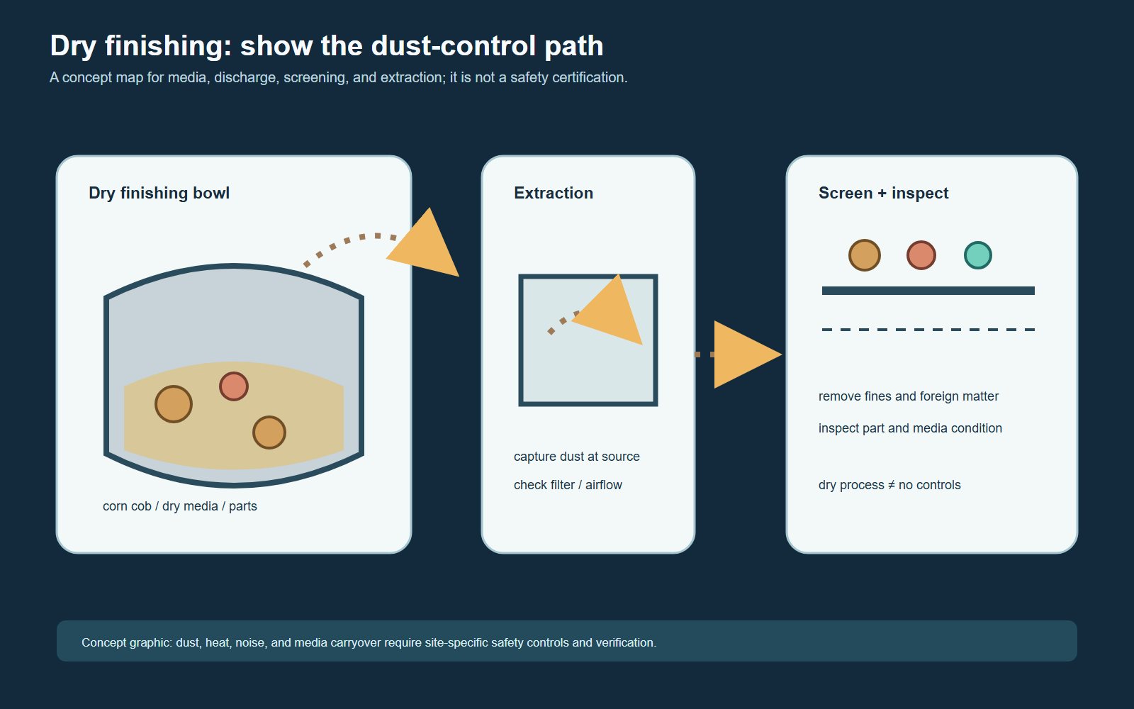
    When Dry Finishing Needs Dust Extraction and Housekeeping Controls Dry mass finishing can generate or release fine particles from media wear, workpiece residue and handling. Whether a process needs local exhaust ventilation, enclosed transfer or additional housekeeping controls must be decided from the actual dust, material safety information, machine arrangement and workplace risk assessment. A finishing-machine setting alone cannot answer that question. Start with the material and dust hazard Identify every material entering the process: workpieces, dry media, additives, coatings and residues. Review the current safety data supplied for each material and determine what dust may be generated during finishing, screening, unloading and cleaning. Do not assume that a dust is harmless because the bulk material appears familiar. Some finely divided materials can create respiratory, fire or deflagration hazards. OSHA notes that combustible dust hazards can occur with materials including metals, plastics, wood and rubber. The exact hazard and required controls depend on the real dust and facility, so testing and competent safety review may be necessary. Look beyond the finishing bowl Dust release can occur at loading, during machine operation, at discharge, through screening, when media is returned and while containers or filters are handled. Walk the complete material route and record visible escape points, settled deposits and tasks that disturb dust. A clean machine exterior does not prove that ducts, ledges or downstream handling points are clean. Conceptual dry-finishing flow: verify the actual capture points, dust properties and safety requirements before specifying extraction equipment. When local exhaust ventilation should be evaluated Local exhaust ventilation is intended to capture an airborne contaminant close to where it is generated. HSE guidance emphasizes that effective LEV depends on suitable hood design, ducts, air movers, air cleaning, commissioning, checking and maintenance. A generic fan or an unverified connection is not evidence of adequate control. Evaluate LEV when dust becomes airborne during normal work, escapes at transfer points, accumulates around the process, or when the material risk assessment calls for engineering control. Capture design must match the source and task without disrupting safe machine operation or spreading contamination to another area. Housekeeping is part of process control A written cleaning routine should identify areas, methods, frequency, responsibility and evidence of completion. Include floors and accessible surfaces as well as beams, cable trays, machine frames, enclosure edges and collection points where dust can settle. Cleaning frequency should be based on observed accumulation and the assessed hazard, not an invented universal interval. Avoid cleaning methods that disperse settled dust into the air. OSHA guidance specifically warns against using compressed air to clear dust surfaces where co...
    View More
  • Frequency, Amplitude and Cycle Time in Vibratory Finishing
    Frequency, Amplitude and Cycle Time in Vibratory Finishing August 03, 2026
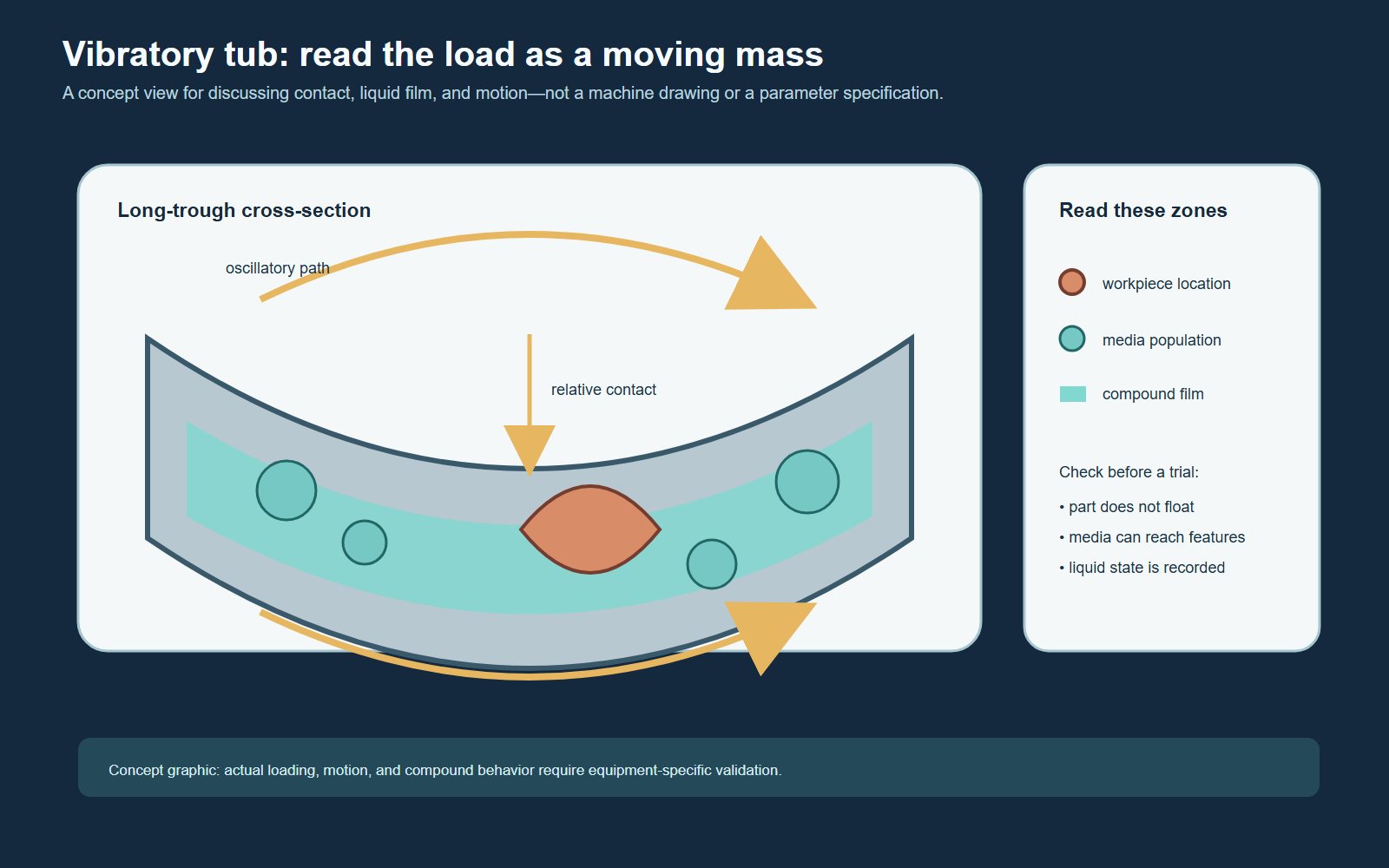
    Frequency, Amplitude and Cycle Time in Vibratory Finishing Frequency, amplitude and cycle time should be treated as interacting trial variables, not independent "more is better" controls. A change in machine motion alters how media and parts circulate, how often they contact, and how force is distributed. The useful setting is the one that produces stable flow and the required edge or surface condition without creating contact damage, lodging, residue or unnecessary dimensional change. Define the result before changing a setting Start with the incoming condition and the feature that matters: a burr location, tool mark, edge requirement, cosmetic face or cleaning issue. Record the inspection method before the trial. "Looks better" is not enough when a buyer also needs protected dimensions, repeatable separation and consistent results across the load. Machine settings cannot be selected from part material alone. Part geometry, media shape and wear, load condition, compound and water state all influence the motion and contact pattern. Use the vibratory finishing troubleshooting guide if the starting problem is a defect rather than a process-development question. What frequency changes in a vibratory trial Frequency describes how often the system oscillates. In practice, it contributes to the motion of the media mass and the repeated contact events around the workpiece. A setting change should therefore be assessed through observable circulation, part movement and surface evidence, not through the control value alone. Watch for dead zones, unstable flow, parts collecting in one area, excessive part exposure or changes in the sound and behavior of the load. These observations do not diagnose a setting by themselves, but they help identify whether the trial remains mechanically stable enough to compare. What amplitude changes in the contact pattern Amplitude describes the size of the oscillatory movement. Its effect depends on the machine, load and media system. A larger motion can change transport and contact severity, but it does not guarantee faster or better finishing. It may also change part-on-part exposure, thin-edge risk or the way compound and debris move through the load. When contact damage is a concern, review media coverage and loading controls with the part-on-part damage prevention guide. Do not try to solve every defect with motion settings. Why cycle time cannot be chosen separately Cycle time is accumulated exposure under a defined process condition. If frequency, amplitude, media condition, load or liquid control changes, the meaning of the same elapsed time changes too. Extending a cycle may increase edge or surface change, but it can also increase wear, contact marks, residue risk or variation. The correct stopping point must be tied to inspection evidence. Use a one-variable trial ladder A controlled comparison changes one variable while holding the part lot, media, load and inspection method stable. Hold the part lot, media, load...
    View More
  • Ceramic Media Shape Guide: Cylinders, Triangles, Cones and Angle Cuts
    Ceramic Media Shape Guide: Cylinders, Triangles, Cones and Angle Cuts August 01, 2026
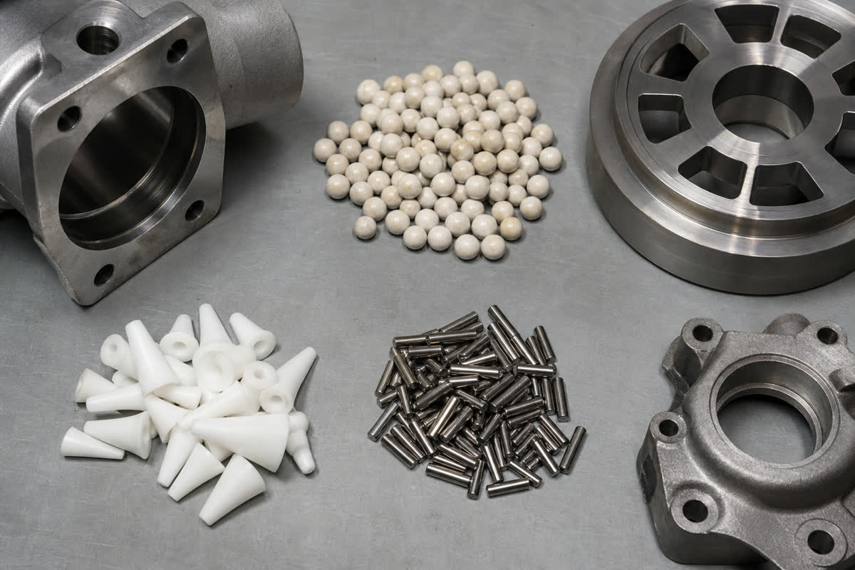
    Ceramic Media Shape Guide: Cylinders, Triangles, Cones and Angle Cuts Choosing ceramic media shape is a geometry decision, not a shortcut based on a shape name. Cylinders, triangles, angle-cut pieces and other profiles contact edges, flats, recesses and openings differently. Start with the part drawing and the features that must be reached or protected, then screen candidate media against lodging, separation and finish risks in a controlled sample trial. Start with the feature, not the media catalogue Before comparing shapes, mark the part features that control the decision: outside edges, broad faces, slots, holes, thread entrances, blind pockets and thin walls. Also record which surfaces may accept edge change and which must retain their original geometry. A media shape that reaches one feature can bridge across another, lodge in an opening or leave a witness pattern on a cosmetic face. Use the part drawing to identify the smallest accessible opening and any two-point or three-point trapping condition. Nominal media dimensions alone are not enough because media wears and the effective contact geometry changes during use. For openings and internal features, use the separate media-size guide for holes, slots and cavities. AI-generated conceptual illustration; not a real factory, customer case or measured result. How common ceramic media shapes change contact Cylinders and angle-cut cylinders Cylindrical media offers a combination of curved side contact and end contact. Angle-cut ends can present narrower contact lines to edges and shallow features. The practical question is whether the cylinder can circulate freely around the part without aligning across a slot or entering a hole where it cannot be separated. Triangles and triangular profiles Triangular media presents corners and flat faces. This can make it useful when a trial needs more defined access near edges or into open recesses, but the same geometry creates orientation-dependent contact. Check whether a triangle can wedge across a feature, mark a protected face or become trapped as it wears. Cones and tapered profiles Tapered media can approach openings with different contact widths along its length. That does not mean it will safely enter every recess. Compare the full profile with the opening, depth and exit path, and inspect for bridging or wedging after each trial step. Stars and other complex profiles Complex profiles provide multiple contact points, but their fit and separation behavior are highly part-dependent. Do not select them simply because they appear more aggressive. Confirm that their arms or lobes cannot catch on cross-holes, slots, threads or thin features, and verify that the worn profile remains separable. Shape is only one part of media selection Ceramic formulation, abrasive behavior, density, size, wear state and the machine motion all affect the result. Water and compound conditions also influence transport, cleanliness and residue. Treat the shape comparison as on...
    View More
1 ... 9 10 11 12

A total of 12 pages

#+86-592-2381506

Email : info@surface-polish.com

Headquarters address : No. 31, Xinchang Road, Xinyang Industrial Zone, Haicang District, Xiamen

click here to leave a message

Leave A Message
If you are interested in our products and want to know more details,please leave a message here,we will reply you as soon as we can.

Home

Products

whatsapp

contact