• How to Choose Media Size for Small Holes, Slots and Internal Cavities
    How to Choose Media Size for Small Holes, Slots and Internal Cavities Jul 27 , 2026
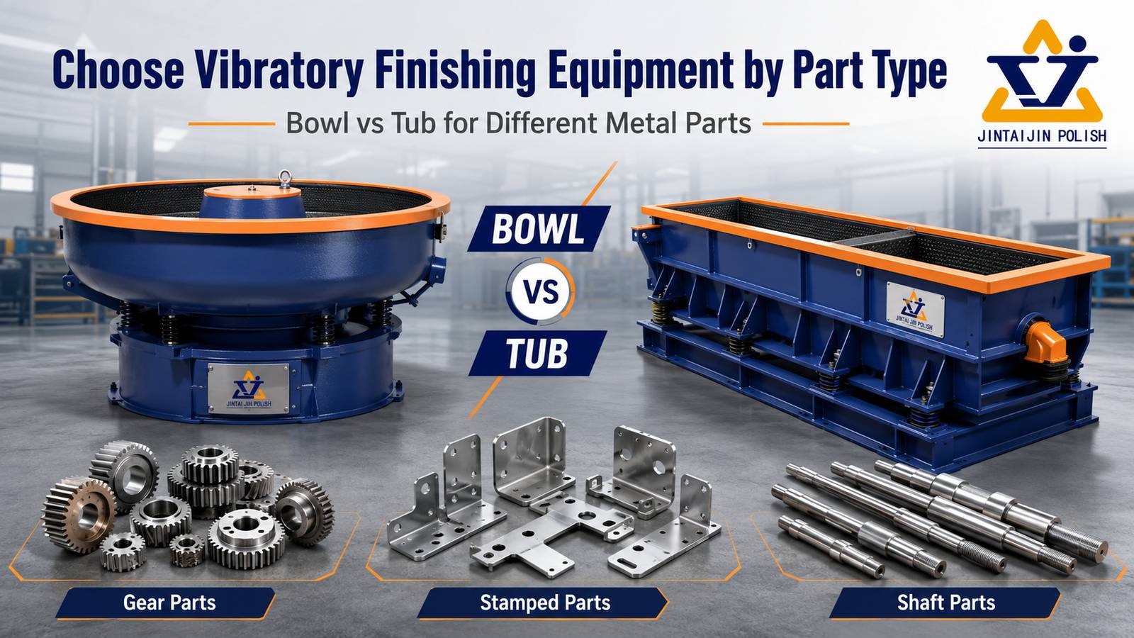
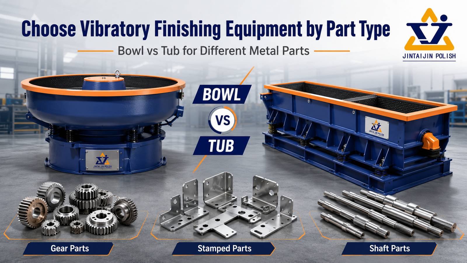
    How to Choose Media Size for Small Holes, Slots and Internal Cavities How to Choose Media Size for Small Holes, Slots and Internal Cavities Short answer: choose the smallest media that reaches the required feature and can still be separated reliably. A smaller chip may improve access, but it can also lodge in a hole, pass through a slot, slow separation or change the contact intensity. The correct size is therefore a geometry, defect, machine and inspection decision—not a simple “smaller is better” rule. Important: confirm media access and separation on representative parts. A catalog size is not proof that a particular shape will pass through your feature without becoming trapped. 1. Map the feature before selecting media Record the smallest opening, slot width, cavity depth and passage length. Also mark threads, sealing faces, cosmetic surfaces and edges that must not be over-rounded. The critical dimension is often not the nominal hole diameter: an angled entry, burr, cross-hole or blind cavity can reduce the usable passage. Through holes: check entry and exit burrs, cross-sections and the chance of a chip passing through and becoming trapped elsewhere.Slots: compare the shortest slot dimension with the media's smallest cross-section and orientation.Blind cavities: check whether media can enter, circulate and leave without packing at the bottom.Internal channels: confirm that the process objective is reachable; surface contact inside a channel may be uneven. 2. Use a fit-and-function screen, not only a size label QuestionWhy it mattersTrial check Can the media enter?A large or poorly oriented shape may never reach the burr.Mark entry and exit; inspect after a short cycle. Can the media leave?Trapped chips create rework, contamination and customer risk.Count retained pieces after separation and washing. Can it protect the edge?Too small or too sharp a contact can increase edge rounding.Measure edge radius and critical dimensions. Media shape changes the effective cross-section. Cylinders, triangles, angle-cut shapes and plastic forms do not enter the same feature in the same way. Select a shape and size together, then check the machine's circulation and separation method. 3. Balance access with lodging and separation Reducing media size may improve access but can make separation slower, especially when the workpiece has many small openings or when the media approaches the feature size. Review the machine's screen, magnetic, flow or vibration separation method before approving a fine media grade. The ceramic versus plastic media guide explains why media family and shape must be considered with geometry. Do not rely on visual shake-out alone. Use a defined retention check, such as a counted sample, flushing step or controlled inspection of cavities. The acceptance method should match the part's risk and customer requirements. 4. Match size to the incoming defect and target finish A small media chip may reach a cavity but lack the mass or cutting action needed to remove a heavy burr. Conversely, a large aggressive media can remove material quickly on an exposed edge while missing the internal feature. Separate the objectives: internal burr removal, surface smoothing, edge radiusing and final polishing may require different stages or machine concepts. For delicate or high-value parts, compare loose bulk finishing with a process that holds the workpiece, such as drag or stream finishing. The machine choice should follow the geometry and damage risk, not the media label alone. 5. A repeatable media-size trial Measure and record the smallest opening, depth and passage length.Select two candidate shapes and two sizes that can be separated by the available equipment.Run a short access trial, then inspect every critical cavity for retained media.Measure burr removal, edge radius, roughness or visual finish as specified.Run the best candidate again with a fresh sample to confirm repeatability.Document the media, machine, load, compound/water, cycle time and separation method. Use the mass-finishing sample trial record to document the size decision and release criteria. For broader machine capacity choices, see the bowl and tub selection guide. Buyer checklistSmallest opening, slot width, cavity depth and passage lengthIncoming burr height and target edge radiusMaterial, hardness, critical dimensions and cosmetic facesCandidate media shape, size and separation methodMachine type, load ratio, compound/water and cycle timeRetention acceptance method and documented release criteria Need help selecting media for internal features?Send the part drawing or photos, smallest passage, incoming burr and target finish. We can help define an access, separation and inspection trial before equipment or media are finalized.Contact SurfacePolish for a process review This guide is a process-selection framework. Final media size, shape and cycle must be confirmed on representative parts.
  • How to Choose Media Size for Small Holes, Slots and Internal Cavities
    How to Choose Media Size for Small Holes, Slots and Internal Cavities Jul 27 , 2026
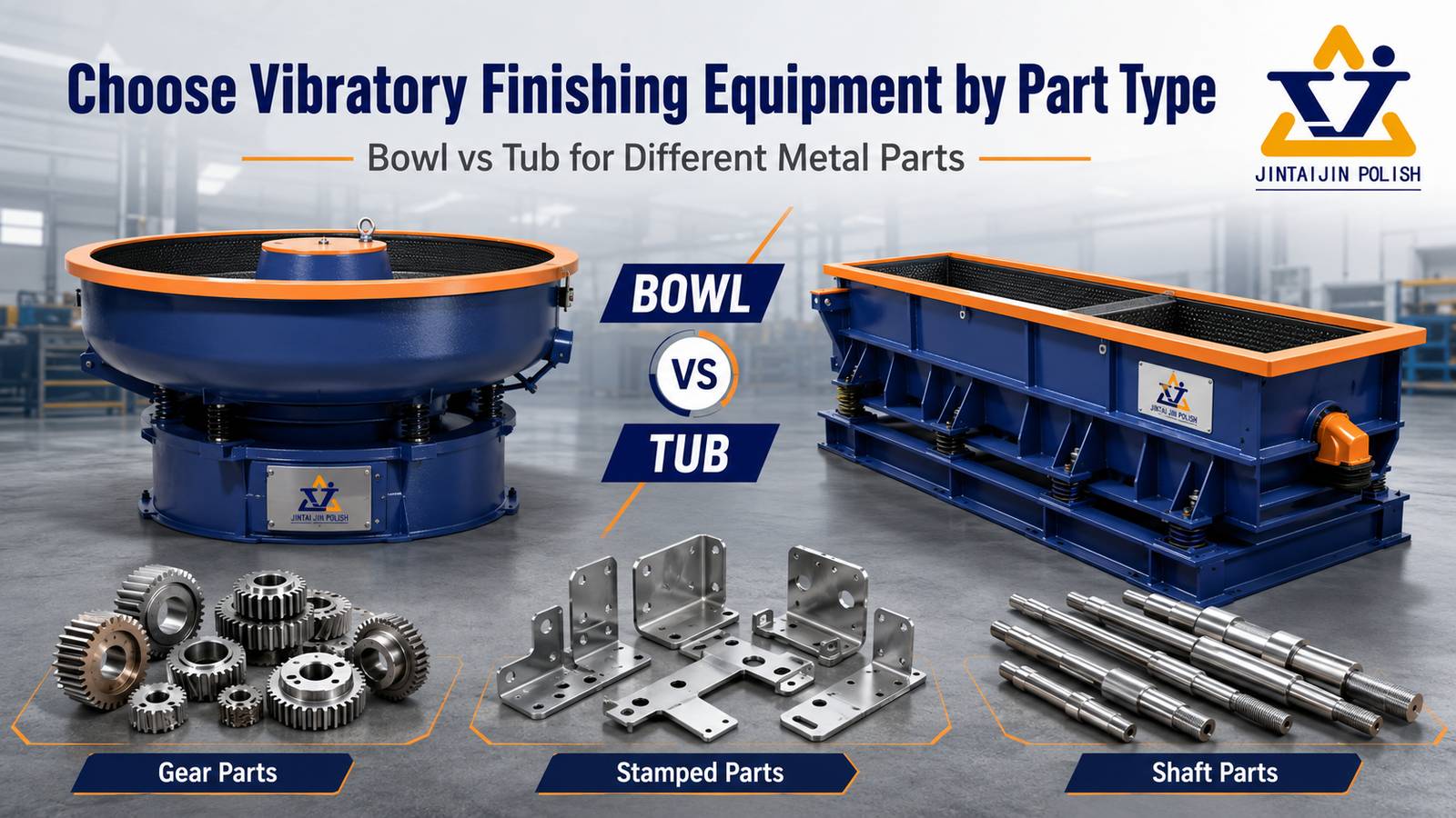
    How to Choose Media Size for Small Holes, Slots and Internal Cavities How to Choose Media Size for Small Holes, Slots and Internal Cavities Short answer: choose the smallest media that reaches the required feature and can still be separated reliably. A smaller chip may improve access, but it can also lodge in a hole, pass through a slot, slow separation or change the contact intensity. The correct size is therefore a geometry, defect, machine and inspection decision—not a simple “smaller is better” rule. Important: confirm media access and separation on representative parts. A catalog size is not proof that a particular shape will pass through your feature without becoming trapped. 1. Map the feature before selecting media Record the smallest opening, slot width, cavity depth and passage length. Also mark threads, sealing faces, cosmetic surfaces and edges that must not be over-rounded. The critical dimension is often not the nominal hole diameter: an angled entry, burr, cross-hole or blind cavity can reduce the usable passage. Through holes: check entry and exit burrs, cross-sections and the chance of a chip passing through and becoming trapped elsewhere.Slots: compare the shortest slot dimension with the media's smallest cross-section and orientation.Blind cavities: check whether media can enter, circulate and leave without packing at the bottom.Internal channels: confirm that the process objective is reachable; surface contact inside a channel may be uneven. 2. Use a fit-and-function screen, not only a size label QuestionWhy it mattersTrial check Can the media enter?A large or poorly oriented shape may never reach the burr.Mark entry and exit; inspect after a short cycle. Can the media leave?Trapped chips create rework, contamination and customer risk.Count retained pieces after separation and washing. Can it protect the edge?Too small or too sharp a contact can increase edge rounding.Measure edge radius and critical dimensions. Media shape changes the effective cross-section. Cylinders, triangles, angle-cut shapes and plastic forms do not enter the same feature in the same way. Select a shape and size together, then check the machine's circulation and separation method. 3. Balance access with lodging and separation Reducing media size may improve access but can make separation slower, especially when the workpiece has many small openings or when the media approaches the feature size. Review the machine's screen, magnetic, flow or vibration separation method before approving a fine media grade. The ceramic versus plastic media guide explains why media family and shape must be considered with geometry. Do not rely on visual shake-out alone. Use a defined retention check, such as a counted sample, flushing step or controlled inspection of cavities. The acceptance method should match the part's risk and customer requirements. 4. Match size to the incoming defect and target finish A small media chip may reach a cavity but lack the mass or cutting action needed to remove a heavy burr. Conversely, a large aggressive media can remove material quickly on an exposed edge while missing the internal feature. Separate the objectives: internal burr removal, surface smoothing, edge radiusing and final polishing may require different stages or machine concepts. For delicate or high-value parts, compare loose bulk finishing with a process that holds the workpiece, such as drag or stream finishing. The machine choice should follow the geometry and damage risk, not the media label alone. 5. A repeatable media-size trial Measure and record the smallest opening, depth and passage length.Select two candidate shapes and two sizes that can be separated by the available equipment.Run a short access trial, then inspect every critical cavity for retained media.Measure burr removal, edge radius, roughness or visual finish as specified.Run the best candidate again with a fresh sample to confirm repeatability.Document the media, machine, load, compound/water, cycle time and separation method. Use the mass-finishing sample trial record to document the size decision and release criteria. For broader machine capacity choices, see the bowl and tub selection guide. Buyer checklistSmallest opening, slot width, cavity depth and passage lengthIncoming burr height and target edge radiusMaterial, hardness, critical dimensions and cosmetic facesCandidate media shape, size and separation methodMachine type, load ratio, compound/water and cycle timeRetention acceptance method and documented release criteria Need help selecting media for internal features?Send the part drawing or photos, smallest passage, incoming burr and target finish. We can help define an access, separation and inspection trial before equipment or media are finalized.Contact SurfacePolish for a process review This guide is a process-selection framework. Final media size, shape and cycle must be confirmed on representative parts.
  • How to Choose Media Size for Small Holes, Slots and Internal Cavities
    How to Choose Media Size for Small Holes, Slots and Internal Cavities Jul 27 , 2026
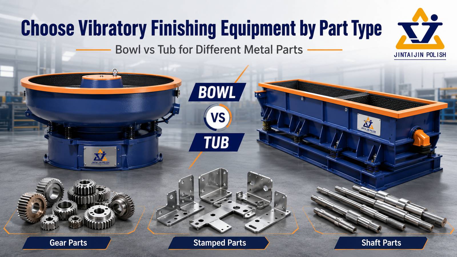
    How to Choose Media Size for Small Holes, Slots and Internal Cavities How to Choose Media Size for Small Holes, Slots and Internal Cavities Short answer: choose the smallest media that reaches the required feature and can still be separated reliably. A smaller chip may improve access, but it can also lodge in a hole, pass through a slot, slow separation or change the contact intensity. The correct size is therefore a geometry, defect, machine and inspection decision—not a simple “smaller is better” rule. Important: confirm media access and separation on representative parts. A catalog size is not proof that a particular shape will pass through your feature without becoming trapped. 1. Map the feature before selecting media Record the smallest opening, slot width, cavity depth and passage length. Also mark threads, sealing faces, cosmetic surfaces and edges that must not be over-rounded. The critical dimension is often not the nominal hole diameter: an angled entry, burr, cross-hole or blind cavity can reduce the usable passage. Through holes: check entry and exit burrs, cross-sections and the chance of a chip passing through and becoming trapped elsewhere.Slots: compare the shortest slot dimension with the media's smallest cross-section and orientation.Blind cavities: check whether media can enter, circulate and leave without packing at the bottom.Internal channels: confirm that the process objective is reachable; surface contact inside a channel may be uneven. 2. Use a fit-and-function screen, not only a size label QuestionWhy it mattersTrial check Can the media enter?A large or poorly oriented shape may never reach the burr.Mark entry and exit; inspect after a short cycle. Can the media leave?Trapped chips create rework, contamination and customer risk.Count retained pieces after separation and washing. Can it protect the edge?Too small or too sharp a contact can increase edge rounding.Measure edge radius and critical dimensions. Media shape changes the effective cross-section. Cylinders, triangles, angle-cut shapes and plastic forms do not enter the same feature in the same way. Select a shape and size together, then check the machine's circulation and separation method. 3. Balance access with lodging and separation Reducing media size may improve access but can make separation slower, especially when the workpiece has many small openings or when the media approaches the feature size. Review the machine's screen, magnetic, flow or vibration separation method before approving a fine media grade. The ceramic versus plastic media guide explains why media family and shape must be considered with geometry. Do not rely on visual shake-out alone. Use a defined retention check, such as a counted sample, flushing step or controlled inspection of cavities. The acceptance method should match the part's risk and customer requirements. 4. Match size to the incoming defect and target finish A small media chip may reach a cavity but lack the mass or cutting action needed to remove a heavy burr. Conversely, a large aggressive media can remove material quickly on an exposed edge while missing the internal feature. Separate the objectives: internal burr removal, surface smoothing, edge radiusing and final polishing may require different stages or machine concepts. For delicate or high-value parts, compare loose bulk finishing with a process that holds the workpiece, such as drag or stream finishing. The machine choice should follow the geometry and damage risk, not the media label alone. 5. A repeatable media-size trial Measure and record the smallest opening, depth and passage length.Select two candidate shapes and two sizes that can be separated by the available equipment.Run a short access trial, then inspect every critical cavity for retained media.Measure burr removal, edge radius, roughness or visual finish as specified.Run the best candidate again with a fresh sample to confirm repeatability.Document the media, machine, load, compound/water, cycle time and separation method. Use the mass-finishing sample trial record to document the size decision and release criteria. For broader machine capacity choices, see the bowl and tub selection guide. Buyer checklistSmallest opening, slot width, cavity depth and passage lengthIncoming burr height and target edge radiusMaterial, hardness, critical dimensions and cosmetic facesCandidate media shape, size and separation methodMachine type, load ratio, compound/water and cycle timeRetention acceptance method and documented release criteria Need help selecting media for internal features?Send the part drawing or photos, smallest passage, incoming burr and target finish. We can help define an access, separation and inspection trial before equipment or media are finalized.Contact SurfacePolish for a process review This guide is a process-selection framework. Final media size, shape and cycle must be confirmed on representative parts.
  • How to Choose Media Size for Small Holes, Slots and Internal Cavities
    How to Choose Media Size for Small Holes, Slots and Internal Cavities Jul 27 , 2026
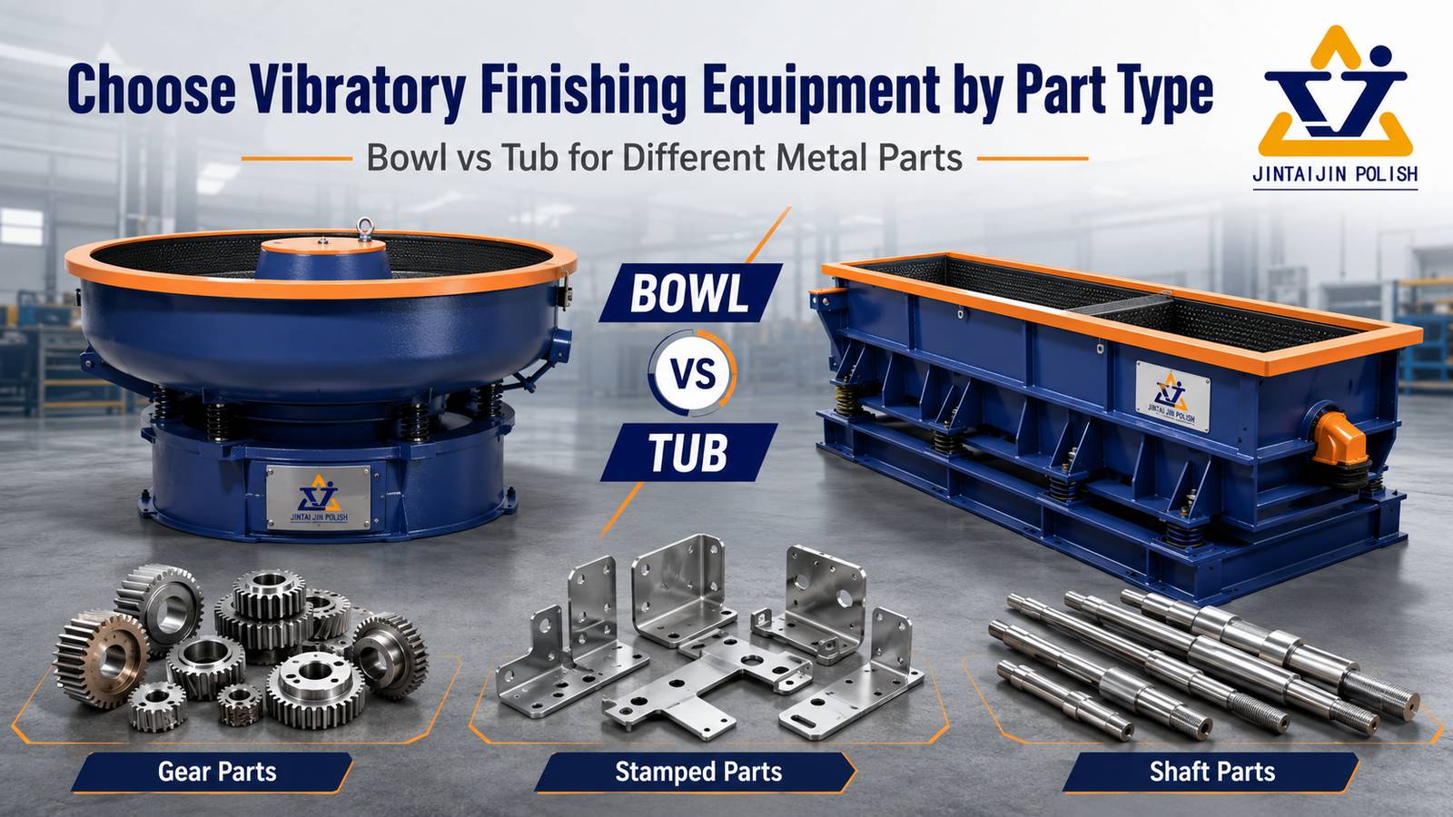
    How to Choose Media Size for Small Holes, Slots and Internal Cavities How to Choose Media Size for Small Holes, Slots and Internal Cavities Short answer: choose the smallest media that reaches the required feature and can still be separated reliably. A smaller chip may improve access, but it can also lodge in a hole, pass through a slot, slow separation or change the contact intensity. The correct size is therefore a geometry, defect, machine and inspection decision—not a simple “smaller is better” rule. Important: confirm media access and separation on representative parts. A catalog size is not proof that a particular shape will pass through your feature without becoming trapped. 1. Map the feature before selecting media Record the smallest opening, slot width, cavity depth and passage length. Also mark threads, sealing faces, cosmetic surfaces and edges that must not be over-rounded. The critical dimension is often not the nominal hole diameter: an angled entry, burr, cross-hole or blind cavity can reduce the usable passage. Through holes: check entry and exit burrs, cross-sections and the chance of a chip passing through and becoming trapped elsewhere.Slots: compare the shortest slot dimension with the media's smallest cross-section and orientation.Blind cavities: check whether media can enter, circulate and leave without packing at the bottom.Internal channels: confirm that the process objective is reachable; surface contact inside a channel may be uneven. 2. Use a fit-and-function screen, not only a size label QuestionWhy it mattersTrial check Can the media enter?A large or poorly oriented shape may never reach the burr.Mark entry and exit; inspect after a short cycle. Can the media leave?Trapped chips create rework, contamination and customer risk.Count retained pieces after separation and washing. Can it protect the edge?Too small or too sharp a contact can increase edge rounding.Measure edge radius and critical dimensions. Media shape changes the effective cross-section. Cylinders, triangles, angle-cut shapes and plastic forms do not enter the same feature in the same way. Select a shape and size together, then check the machine's circulation and separation method. 3. Balance access with lodging and separation Reducing media size may improve access but can make separation slower, especially when the workpiece has many small openings or when the media approaches the feature size. Review the machine's screen, magnetic, flow or vibration separation method before approving a fine media grade. The ceramic versus plastic media guide explains why media family and shape must be considered with geometry. Do not rely on visual shake-out alone. Use a defined retention check, such as a counted sample, flushing step or controlled inspection of cavities. The acceptance method should match the part's risk and customer requirements. 4. Match size to the incoming defect and target finish A small media chip may reach a cavity but lack the mass or cutting action needed to remove a heavy burr. Conversely, a large aggressive media can remove material quickly on an exposed edge while missing the internal feature. Separate the objectives: internal burr removal, surface smoothing, edge radiusing and final polishing may require different stages or machine concepts. For delicate or high-value parts, compare loose bulk finishing with a process that holds the workpiece, such as drag or stream finishing. The machine choice should follow the geometry and damage risk, not the media label alone. 5. A repeatable media-size trial Measure and record the smallest opening, depth and passage length.Select two candidate shapes and two sizes that can be separated by the available equipment.Run a short access trial, then inspect every critical cavity for retained media.Measure burr removal, edge radius, roughness or visual finish as specified.Run the best candidate again with a fresh sample to confirm repeatability.Document the media, machine, load, compound/water, cycle time and separation method. Use the mass-finishing sample trial record to document the size decision and release criteria. For broader machine capacity choices, see the bowl and tub selection guide. Buyer checklistSmallest opening, slot width, cavity depth and passage lengthIncoming burr height and target edge radiusMaterial, hardness, critical dimensions and cosmetic facesCandidate media shape, size and separation methodMachine type, load ratio, compound/water and cycle timeRetention acceptance method and documented release criteria Need help selecting media for internal features?Send the part drawing or photos, smallest passage, incoming burr and target finish. We can help define an access, separation and inspection trial before equipment or media are finalized.Contact SurfacePolish for a process review This guide is a process-selection framework. Final media size, shape and cycle must be confirmed on representative parts.
  • How to Prevent Part-on-Part Damage in Vibratory Finishing
    How to Prevent Part-on-Part Damage in Vibratory Finishing Jul 24 , 2026
    How to Prevent Part-on-Part Damage in Vibratory Finishing How to Prevent Part-on-Part Damage in Vibratory Finishing Short answer: part-on-part damage is usually a contact-control problem. Protect the workpieces with enough media coverage, a suitable media size and shape, a stable load ratio and a machine motion that keeps parts separated. Confirm the change with before-and-after inspection instead of assuming that a softer media or shorter cycle will solve every defect. Important: the same scratch or dent can have different causes, including direct workpiece contact, media lodging, contamination or an aggressive process. Use a controlled trial to isolate one variable at a time. 1. Identify the damage before changing the process Record where the defect appears and when it is introduced. Map cosmetic faces, thin walls, threads, sealing surfaces and sharp edges. A repeated mark on a mating face suggests a different control problem from random dents on an exposed corner. Scratches: check trapped chips, broken media, contamination and sliding contact.Dents or impact marks: check direct part contact, drop height, fill level and excessive machine intensity.Edge damage: check media shape, unsupported features and over-processing.Uneven damage: check loading pattern, circulation and whether parts are segregating in the bowl or tub. 2. Keep workpieces separated with media coverage Media should surround the parts so that workpieces are not repeatedly striking each other. A low media-to-part ratio can expose the parts; an overloaded machine can restrict circulation and create local contact. Start from the machine supplier's recommended fill range, then confirm actual movement with a representative load. Small openings and recessed features need special attention. Media that is too large may not protect an internal surface, while media that is too small can lodge in holes or become difficult to separate. For a broader machine and capacity decision, see the bowl and tub selection guide. 3. Match media shape and hardness to the risk Observed riskTrial directionWhat to measure Impact on cosmetic facesLower-impact media, more coverage, lower intensityDent count, visual grade, cycle time Scratches from contaminationClean media, screen fines, separate material familiesScratch length, residue, media condition Thin features contacting each otherChange loading, reduce drop/contact intensity, consider fixturingBend, dent depth, dimensional change Media selection should remain tied to the finishing objective. A more aggressive cutting media may remove a burr faster but can also increase edge rounding or impact risk. Review the ceramic versus plastic media guide before changing media family. 4. Control machine motion, load and cycle time Machine type changes how parts circulate, slide and separate. Bowl vibrators, tubs, rotary barrels and centrifugal systems do not create the same contact pattern. Check amplitude or speed, load ratio, media fill, water and compound condition, and actual cycle time. If damage increases late in the cycle, the process may be stable initially but over-processing the surface. Do not solve a contact problem only by reducing time if the incoming burr or contamination remains. Instead, compare a small process matrix and retain the best result in a trial record. 5. A repeatable trial for separating part-on-part causes Photograph and label ten representative parts before processing.Mark critical faces and record incoming burrs, scratches and dimensions.Run a baseline load, then change only one variable: media coverage, media shape, machine intensity or cycle time.Inspect after a short interval and at the final interval; do not inspect only the final batch.Record dents, scratches, edge radius, residue and media separation results.Repeat the best setting with a second sample to confirm that the result is stable. The mass-finishing sample trial record provides a practical structure for recording the variables and release decision. 6. When to consider fixturing or another finishing process Some geometries cannot be protected reliably by loose media alone. Thin blades, delicate cosmetic faces, deep cavities and parts with strict edge-radius limits may need fixturing, a different machine family or a dedicated finishing stage. Treat this as an engineering decision, not a failure of the operator to find the right cycle. Buyer checklistWhere does the damage appear and what does it look like?What are the part material, hardness, weight and critical surfaces?What is the smallest hole, slot or recess that media must access?What are the current media size, shape, fill and condition?What machine, speed/frequency, load and cycle time are being used?Which dimensions, edge radius or cosmetic standard must be released? Need help reducing contact damage?Share the part drawing or photos, incoming defect, target finish, current machine and media details. We can help define a controlled sample trial and identify the variables that need confirmation.Contact SurfacePolish for a process review This guide is an engineering selection framework. Final media, machine and cycle decisions should be confirmed on representative parts and documented with inspection results.
  • How to Choose Ceramic vs Plastic Media for Aluminum, Brass and Steel Parts
    How to Choose Ceramic vs Plastic Media for Aluminum, Brass and Steel Parts Jul 23 , 2026
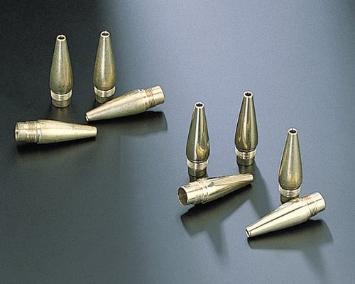
    Ceramic vs Plastic Tumbling Media for Aluminum, Brass and Steel Parts How to Choose Ceramic vs Plastic Media for Aluminum, Brass and Steel Parts Short answer: choose ceramic media when controlled cutting, burr removal or edge radiusing is the priority; choose plastic media when a lower-impact, lighter-contact process is needed for softer metals, cosmetic surfaces or a finer finishing stage. The correct choice still depends on part geometry, incoming defects, target finish, machine motion and trial results. Important: media selection is a process decision, not a universal material rule. Supplier pages describe product capabilities; research papers describe mechanisms under specific conditions. Confirm the result on representative parts before approving a production recipe. 1. Start with the finishing objective Separate the objective into one primary target and any secondary targets: Deburring: remove a defined burr without damaging threads, holes or sealing faces. Edge radiusing: create a controlled edge radius rather than simply making the edge “smooth.” Smoothing: reduce peaks and blend machining or casting marks. Polishing: improve brightness or reduce roughness after a suitable pre-finish. Cleaning: remove oil, scale or loose residue without over-processing the part. Open research links material removal and surface topography to particle contacts, process parameters and initial surface condition. That is why the same media can behave differently on two parts that look similar but have different burr height, hardness or geometry. 2. Ceramic vs plastic: a practical comparison Decision factorCeramic mediaPlastic media Typical roleCutting, deburring, edge radiusing, surface grindingLower-impact smoothing, polishing and separation-sensitive work Contact behaviorHigher density can increase contact pressure and cutting actionLighter contact can reduce impact on softer or cosmetic surfaces Common fitSteel, iron, aluminum, brass and difficult burrsAluminum, brass, plastics and parts where impact marks are a concern Main risksExcess edge rounding, media lodging or cosmetic impact if over-aggressiveLonger cycle, media wear, foam/chemistry sensitivity and insufficient burr removal Best next stepControl shape, size, load and time with edge-radius checksCheck separation, surface appearance, wear and cycle-time stability This comparison is a selection framework synthesized from official media guidance and open finishing research; it is not a promise that every ceramic or plastic formulation will behave identically. 3. Match media to material and geometry Aluminum Aluminum often needs enough cutting action to remove burrs, but excessive impact or unsuitable chemistry can create cosmetic damage or residue. Begin with a less aggressive trial when the part has thin walls, visible faces or sealing surfaces. Use a small enough media size to reach the required features, while checking that it cannot lodge in holes or slots. Brass Brass valves and fittings require protection of threads, seats and sealing faces. Ceramic may be appropriate for controlled burr removal, while plastic may be preferable for a lighter finishing stage. Keep the objective explicit: thread-safe deburring is different from bright cosmetic polishing. See the existing brass valves and fittings guide for part-specific risks. Steel and stainless steel Steel parts can tolerate stronger cutting action than many soft alloys, but the required result may still be a controlled edge break rather than maximum stock removal. For small fasteners, compare burr removal, thread condition and media separation in the same trial record. Use the small fastener deburring guide as the application context. 4. Shape, size and the three failure modes to check Media shape and access Cylinders, triangles, angle-cut shapes and other geometries behave differently in slots, holes and recessed areas. A smaller media size can improve access, but it can also increase separation difficulty or lodging risk. Choose the smallest media that can be separated reliably after the process, not simply the smallest media available. Part-on-part impact Mixed loading, insufficient media coverage or an unsuitable machine motion can allow parts to strike each other. Inspect cosmetic faces, thin walls and sharp features after each trial stage. If contact damage is unacceptable, investigate fixturing, a different machine family or a lower-impact media/process combination. Excess edge rounding Deburring and edge radiusing are not the same as removing as much material as possible. Record burr height before processing and edge radius after processing. If the edge radius grows beyond the drawing or assembly requirement, reduce cutting intensity, cycle time or media aggressiveness before changing the entire machine concept. 5. Machine and compound choices Media cannot be selected independently of the machine. A bowl, tub, rotary barrel, centrifugal unit, drag finisher or magnetic polisher creates a different contact pattern. For a broader bowl-versus-tub and capacity decision, use the existing vibratory machine selection guide. For small precision components and magnetic pins, compare the magnetic polishing machine page. Wet processes also depend on water and compound condition. Track concentration, foam, contamination, pH or conductivity where relevant to the process. Dry finishing uses a different control logic: the medium, paste or powder, dust extraction and housekeeping must be evaluated together. Do not transfer a wet-process cycle directly to dry media. 6. A sample-trial method buyers can repeat Define the incoming condition: material, hardness if known, burr height, surface defects and critical dimensions. Mark critical zones: threads, holes, sealing faces, cosmetic faces and edges requiring a defined radius. Run a small matrix: ceramic vs plastic, two media sizes, and two cycle times. Change one variable at a time where possible. Record machine type, load ratio, media fill, compound/water condition, speed or frequency and actual cycle time. Measure burr height, edge radius, Ra/Sa where specified, visual defects and media separation performance. Keep samples and photographs with the trial record. Approve a recipe only after repeat runs show stable results. Use the printable mass-finishing sample trial record to keep the comparison auditable. 7. Buyer checklist before requesting a quotation Part material, hardness and surface condition Part dimensions, weight, batch size and production target Smallest hole/slot and any media-lodging risk Critical edges, threads, sealing faces and cosmetic surfaces Target burr height, edge radius, roughness or visual standard Wet or dry process preference, water handling and separation requirements Photos or drawings that can be shared for a sample trial Need help selecting media? Send the part material, geometry, incoming defect, target finish and a few representative samples. We can help define a trial matrix and identify the machine, media and compound variables that need confirmation. Request a process discussion Source basis and evidence boundary This article synthesizes public technical information from Rösler, OTEC and Walther Trowal with open research on material removal, contact conditions, roughness measurement and additive-manufacturing post-processing. Manufacturer pages describe their own systems and consumables; research results apply to their stated test conditions. Production parameters, finish guarantees and compliance claims require a representative sample trial.
  • How to Choose Ceramic vs Plastic Media for Aluminum, Brass and Steel Parts
    How to Choose Ceramic vs Plastic Media for Aluminum, Brass and Steel Parts Jul 23 , 2026
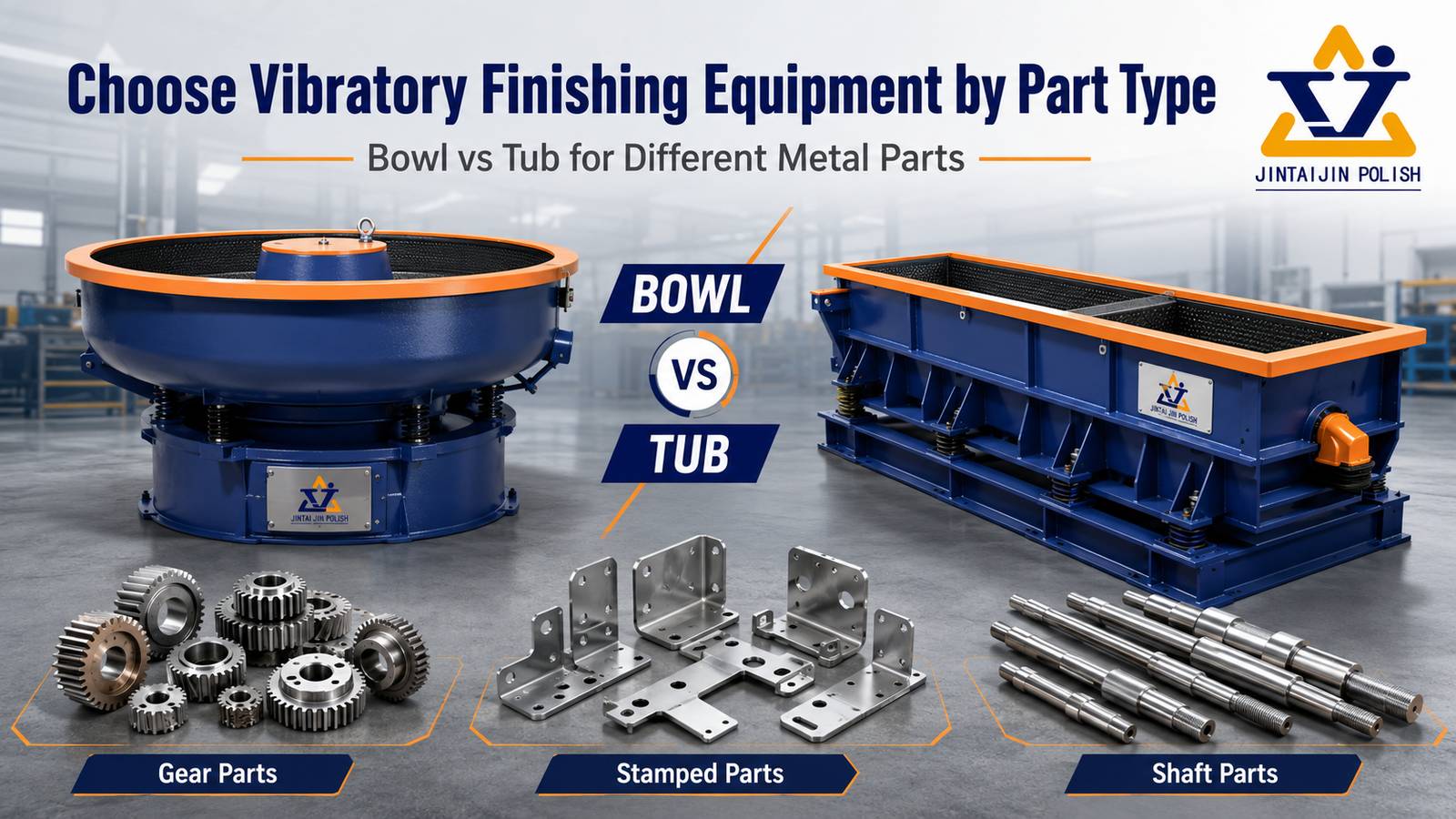
    Ceramic vs Plastic Tumbling Media for Aluminum, Brass and Steel Parts Cover design direction: show the decision, not a generic machine hero. Add English labels “CERAMIC MEDIA” and “PLASTIC MEDIA” only if the cover is redesigned. How to Choose Ceramic vs Plastic Media for Aluminum, Brass and Steel Parts Short answer: choose ceramic media when controlled cutting, burr removal or edge radiusing is the priority; choose plastic media when a lower-impact, lighter-contact process is needed for softer metals, cosmetic surfaces or a finer finishing stage. The correct choice still depends on part geometry, incoming defects, target finish, machine motion and trial results. Important: media selection is a process decision, not a universal material rule. Supplier pages describe product capabilities; research papers describe mechanisms under specific conditions. Confirm the result on representative parts before approving a production recipe. 1. Start with the finishing objective Separate the objective into one primary target and any secondary targets: Deburring: remove a defined burr without damaging threads, holes or sealing faces. Edge radiusing: create a controlled edge radius rather than simply making the edge “smooth.” Smoothing: reduce peaks and blend machining or casting marks. Polishing: improve brightness or reduce roughness after a suitable pre-finish. Cleaning: remove oil, scale or loose residue without over-processing the part. Open research links material removal and surface topography to particle contacts, process parameters and initial surface condition. That is why the same media can behave differently on two parts that look similar but have different burr height, hardness or geometry. 2. Ceramic vs plastic: a practical comparison Decision factorCeramic mediaPlastic media Typical roleCutting, deburring, edge radiusing, surface grindingLower-impact smoothing, polishing and separation-sensitive work Contact behaviorHigher density can increase contact pressure and cutting actionLighter contact can reduce impact on softer or cosmetic surfaces Common fitSteel, iron, aluminum, brass and difficult burrsAluminum, brass, plastics and parts where impact marks are a concern Main risksExcess edge rounding, media lodging or cosmetic impact if over-aggressiveLonger cycle, media wear, foam/chemistry sensitivity and insufficient burr removal Best next stepControl shape, size, load and time with edge-radius checksCheck separation, surface appearance, wear and cycle-time stability This comparison is a selection framework synthesized from official media guidance and open finishing research; it is not a promise that every ceramic or plastic formulation will behave identically. 3. Match media to material and geometry Aluminum Aluminum often needs enough cutting action to remove burrs, but excessive impact or unsuitable chemistry can create cosmetic damage or residue. Begin with a less aggressive trial when the part has thin walls, visible faces or sealing surfaces. Use a small enough media size to reach the required features, while checking that it cannot lodge in holes or slots. Brass Brass valves and fittings require protection of threads, seats and sealing faces. Ceramic may be appropriate for controlled burr removal, while plastic may be preferable for a lighter finishing stage. Keep the objective explicit: thread-safe deburring is different from bright cosmetic polishing. See the existing brass valves and fittings guide for part-specific risks. Steel and stainless steel Steel parts can tolerate stronger cutting action than many soft alloys, but the required result may still be a controlled edge break rather than maximum stock removal. For small fasteners, compare burr removal, thread condition and media separation in the same trial record. Use the small fastener deburring guide as the application context. Image design direction: add a simple English callout layer for “part geometry,” “media access,” and “contact intensity.” 4. Shape, size and the three failure modes to check Media shape and access Cylinders, triangles, angle-cut shapes and other geometries behave differently in slots, holes and recessed areas. A smaller media size can improve access, but it can also increase separation difficulty or lodging risk. Choose the smallest media that can be separated reliably after the process, not simply the smallest media available. Part-on-part impact Mixed loading, insufficient media coverage or an unsuitable machine motion can allow parts to strike each other. Inspect cosmetic faces, thin walls and sharp features after each trial stage. If contact damage is unacceptable, investigate fixturing, a different machine family or a lower-impact media/process combination. Excess edge rounding Deburring and edge radiusing are not the same as removing as much material as possible. Record burr height before processing and edge radius after processing. If the edge radius grows beyond the drawing or assembly requirement, reduce cutting intensity, cycle time or media aggressiveness before changing the entire machine concept. 5. Machine and compound choices Media cannot be selected independently of the machine. A bowl, tub, rotary barrel, centrifugal unit, drag finisher or magnetic polisher creates a different contact pattern. For a broader bowl-versus-tub and capacity decision, use the existing vibratory machine selection guide. For small precision components and magnetic pins, compare the magnetic polishing machine page. Wet processes also depend on water and compound condition. Track concentration, foam, contamination, pH or conductivity where relevant to the process. Dry finishing uses a different control logic: the medium, paste or powder, dust extraction and housekeeping must be evaluated together. Do not transfer a wet-process cycle directly to dry media. 6. A sample-trial method buyers can repeat Define the incoming condition: material, hardness if known, burr height, surface defects and critical dimensions. Mark critical zones: threads, holes, sealing faces, cosmetic faces and edges requiring a defined radius. Run a small matrix: ceramic vs plastic, two media sizes, and two cycle times. Change one variable at a time where possible. Record machine type, load ratio, media fill, compound/water condition, speed or frequency and actual cycle time. Measure burr height, edge radius, Ra/Sa where specified, visual defects and media separation performance. Keep samples and photographs with the trial record. Approve a recipe only after repeat runs show stable results. Use the printable mass-finishing sample trial record to keep the comparison auditable. Image design direction: highlight “Incoming condition,” “Process variables,” “Measurement,” and “Release decision” in English. 7. Buyer checklist before requesting a quotation Part material, hardness and surface condition Part dimensions, weight, batch size and production target Smallest hole/slot and any media-lodging risk Critical edges, threads, sealing faces and cosmetic surfaces Target burr height, edge radius, roughness or visual standard Wet or dry process preference, water handling and separation requirements Photos or drawings that can be shared for a sample trial Need help selecting media? Send the part material, geometry, incoming defect, target finish and a few representative samples. We can help define a trial matrix and identify the machine, media and compound variables that need confirmation. Request a process discussion Source basis and evidence boundary This article synthesizes public technical information from Rösler, OTEC and Walther Trowal with open research on material removal, contact conditions, roughness measurement and additive-manufacturing post-processing. Manufacturer pages describe their own systems and consumables; research results apply to their stated test conditions. Production parameters, finish guarantees and compliance claims require a representative sample trial.
  • How to Choose Ceramic vs Plastic Media for Aluminum, Brass and Steel Parts
    How to Choose Ceramic vs Plastic Media for Aluminum, Brass and Steel Parts Jul 23 , 2026
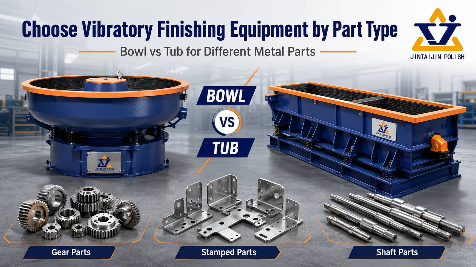
    Ceramic vs Plastic Tumbling Media for Aluminum, Brass and Steel Parts Cover design direction: show the decision, not a generic machine hero. Add English labels “CERAMIC MEDIA” and “PLASTIC MEDIA” only if the cover is redesigned. How to Choose Ceramic vs Plastic Media for Aluminum, Brass and Steel Parts Short answer: choose ceramic media when controlled cutting, burr removal or edge radiusing is the priority; choose plastic media when a lower-impact, lighter-contact process is needed for softer metals, cosmetic surfaces or a finer finishing stage. The correct choice still depends on part geometry, incoming defects, target finish, machine motion and trial results. Important: media selection is a process decision, not a universal material rule. Supplier pages describe product capabilities; research papers describe mechanisms under specific conditions. Confirm the result on representative parts before approving a production recipe. 1. Start with the finishing objective Separate the objective into one primary target and any secondary targets: Deburring: remove a defined burr without damaging threads, holes or sealing faces. Edge radiusing: create a controlled edge radius rather than simply making the edge “smooth.” Smoothing: reduce peaks and blend machining or casting marks. Polishing: improve brightness or reduce roughness after a suitable pre-finish. Cleaning: remove oil, scale or loose residue without over-processing the part. Open research links material removal and surface topography to particle contacts, process parameters and initial surface condition. That is why the same media can behave differently on two parts that look similar but have different burr height, hardness or geometry. 2. Ceramic vs plastic: a practical comparison Decision factorCeramic mediaPlastic media Typical roleCutting, deburring, edge radiusing, surface grindingLower-impact smoothing, polishing and separation-sensitive work Contact behaviorHigher density can increase contact pressure and cutting actionLighter contact can reduce impact on softer or cosmetic surfaces Common fitSteel, iron, aluminum, brass and difficult burrsAluminum, brass, plastics and parts where impact marks are a concern Main risksExcess edge rounding, media lodging or cosmetic impact if over-aggressiveLonger cycle, media wear, foam/chemistry sensitivity and insufficient burr removal Best next stepControl shape, size, load and time with edge-radius checksCheck separation, surface appearance, wear and cycle-time stability This comparison is a selection framework synthesized from official media guidance and open finishing research; it is not a promise that every ceramic or plastic formulation will behave identically. 3. Match media to material and geometry Aluminum Aluminum often needs enough cutting action to remove burrs, but excessive impact or unsuitable chemistry can create cosmetic damage or residue. Begin with a less aggressive trial when the part has thin walls, visible faces or sealing surfaces. Use a small enough media size to reach the required features, while checking that it cannot lodge in holes or slots. Brass Brass valves and fittings require protection of threads, seats and sealing faces. Ceramic may be appropriate for controlled burr removal, while plastic may be preferable for a lighter finishing stage. Keep the objective explicit: thread-safe deburring is different from bright cosmetic polishing. See the existing brass valves and fittings guide for part-specific risks. Steel and stainless steel Steel parts can tolerate stronger cutting action than many soft alloys, but the required result may still be a controlled edge break rather than maximum stock removal. For small fasteners, compare burr removal, thread condition and media separation in the same trial record. Use the small fastener deburring guide as the application context. Image design direction: add a simple English callout layer for “part geometry,” “media access,” and “contact intensity.” 4. Shape, size and the three failure modes to check Media shape and access Cylinders, triangles, angle-cut shapes and other geometries behave differently in slots, holes and recessed areas. A smaller media size can improve access, but it can also increase separation difficulty or lodging risk. Choose the smallest media that can be separated reliably after the process, not simply the smallest media available. Part-on-part impact Mixed loading, insufficient media coverage or an unsuitable machine motion can allow parts to strike each other. Inspect cosmetic faces, thin walls and sharp features after each trial stage. If contact damage is unacceptable, investigate fixturing, a different machine family or a lower-impact media/process combination. Excess edge rounding Deburring and edge radiusing are not the same as removing as much material as possible. Record burr height before processing and edge radius after processing. If the edge radius grows beyond the drawing or assembly requirement, reduce cutting intensity, cycle time or media aggressiveness before changing the entire machine concept. 5. Machine and compound choices Media cannot be selected independently of the machine. A bowl, tub, rotary barrel, centrifugal unit, drag finisher or magnetic polisher creates a different contact pattern. For a broader bowl-versus-tub and capacity decision, use the existing vibratory machine selection guide. For small precision components and magnetic pins, compare the magnetic polishing machine page. Wet processes also depend on water and compound condition. Track concentration, foam, contamination, pH or conductivity where relevant to the process. Dry finishing uses a different control logic: the medium, paste or powder, dust extraction and housekeeping must be evaluated together. Do not transfer a wet-process cycle directly to dry media. 6. A sample-trial method buyers can repeat Define the incoming condition: material, hardness if known, burr height, surface defects and critical dimensions. Mark critical zones: threads, holes, sealing faces, cosmetic faces and edges requiring a defined radius. Run a small matrix: ceramic vs plastic, two media sizes, and two cycle times. Change one variable at a time where possible. Record machine type, load ratio, media fill, compound/water condition, speed or frequency and actual cycle time. Measure burr height, edge radius, Ra/Sa where specified, visual defects and media separation performance. Keep samples and photographs with the trial record. Approve a recipe only after repeat runs show stable results. Use the printable mass-finishing sample trial record to keep the comparison auditable. Image design direction: highlight “Incoming condition,” “Process variables,” “Measurement,” and “Release decision” in English. 7. Buyer checklist before requesting a quotation Part material, hardness and surface condition Part dimensions, weight, batch size and production target Smallest hole/slot and any media-lodging risk Critical edges, threads, sealing faces and cosmetic surfaces Target burr height, edge radius, roughness or visual standard Wet or dry process preference, water handling and separation requirements Photos or drawings that can be shared for a sample trial Need help selecting media? Send the part material, geometry, incoming defect, target finish and a few representative samples. We can help define a trial matrix and identify the machine, media and compound variables that need confirmation. Request a process discussion Source basis and evidence boundary This article synthesizes public technical information from Rösler, OTEC and Walther Trowal with open research on material removal, contact conditions, roughness measurement and additive-manufacturing post-processing. Manufacturer pages describe their own systems and consumables; research results apply to their stated test conditions. Production parameters, finish guarantees and compliance claims require a representative sample trial.
  • Mass Finishing Sample Trial Record for Small Precision Parts
    Mass Finishing Sample Trial Record for Small Precision Parts Jul 20 , 2026
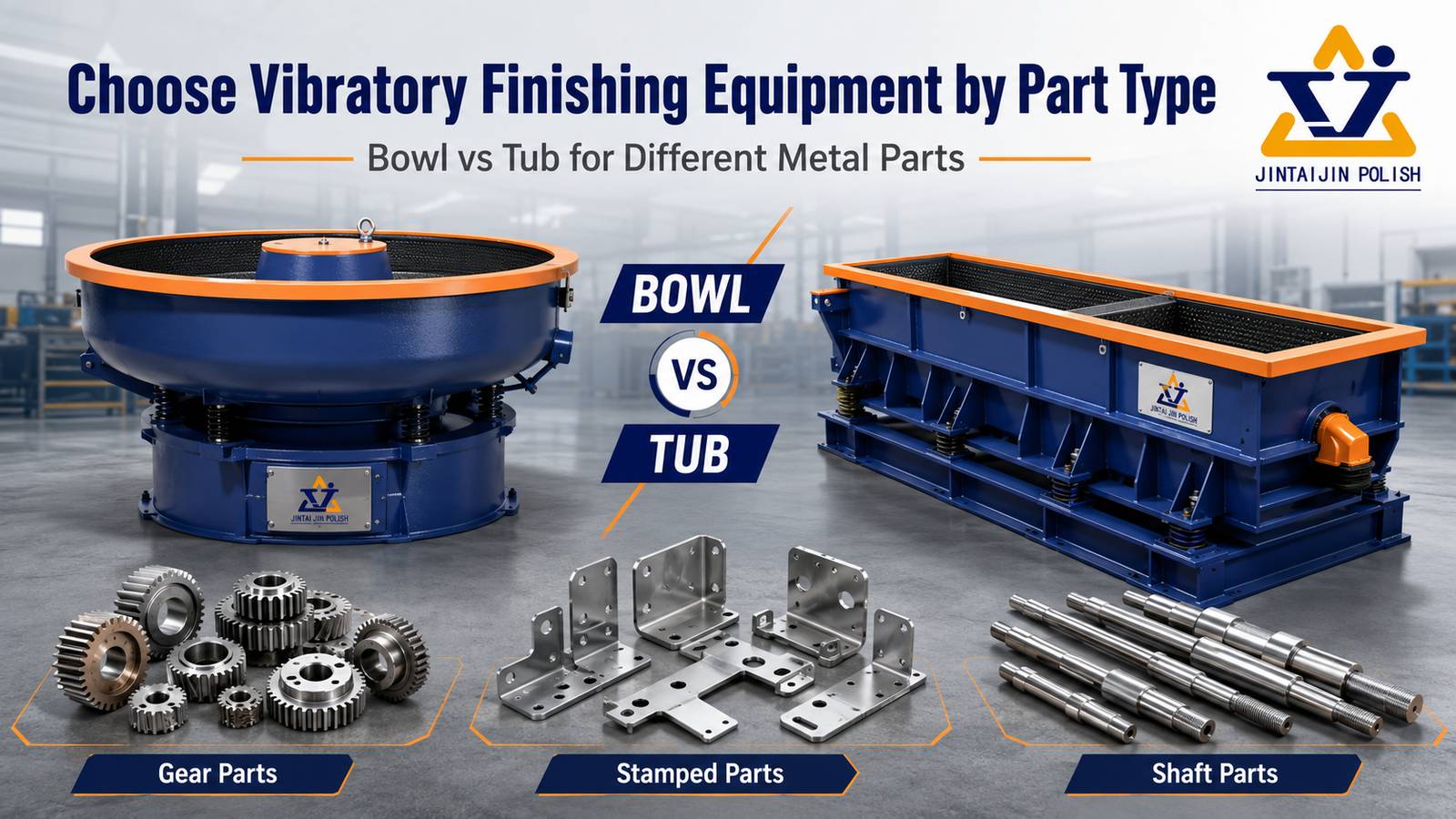
    Printable Process-Control Resource Mass Finishing Sample Trial Record for Small Precision Parts Use this non-promotional worksheet to define the incoming part, record one controlled finishing trial, compare results, and decide whether the process is ready for a repeat run. Important: This record does not replace a drawing, control plan, safety procedure, material compatibility review, or customer specification. Record actual observations and measurements. Do not enter a result that was not inspected. How to use this worksheet Complete the part and acceptance sections before selecting a machine or recipe. Photograph representative parts under consistent lighting and mark the critical inspection locations. Run a small representative batch. Change one primary variable at a time. Inspect at planned intervals instead of extending the cycle by assumption. Repeat an acceptable trial before releasing a process window for production. A. Part and acceptance definition Field Record Trial ID / date / owner   Part name / drawing revision   Material / hardness / coating   Part size / weight / batch quantity   Incoming defect and location   Critical features to protect Threads / holes / slots / sealing face / sharp edge / cosmetic face / other: Acceptance criteria Burr limit, edge condition, dimensions, surface appearance, cleanliness and any approved reference sample: Inspection method Visual standard / magnification / gauge / surface measurement / functional test: B. Trial recipe and load Process field Setting or measured value Why selected Machine / bowl, tub, barrel or magnetic system     Media material / shape / size / condition     Part load / media load / working volume     Compound / water / concentration / flow     Speed / amplitude / direction     Planned inspection times     Separation / rinse / dry method     C. Inspection results by interval Time Burr / defect Critical edges Dimensions Surface / cleanliness Decision 0 / baseline           Interval 1           Interval 2           Final           D. Failure evidence and next change Do not record only “pass” or “fail.” Describe where the result appeared, how many inspected parts showed it, and which process variable will be changed next. Observed pattern Evidence to record Next controlled question Burr remains Location, direction, size range and affected sample count Is contact missing, media too large, or process energy insufficient? Edge changes before burr is removed Critical edge measurement and comparison photo Can energy, interval, media or upstream burr size be reduced? Part-on-part marks or tangling Part orientation, load composition and affected surfaces Does the load need more separation, lower part quantity or different motion? Media lodges in a feature Feature opening, media dimensions, frequency and removal method Which shape or size avoids the dimensional match? E. Repeatability and release Repeat trial ID and number of repeat batches: ____________________ Process window approved, conditional or rejected: ____________________ Variables that must not change without a new trial: ____________________ Inspection frequency for production: ____________________ Approved by / date / drawing or control-plan reference: ____________________ Methodology and related guides The worksheet fields are derived from a basic controlled-trial principle: define acceptance first, document the starting condition, change limited variables, inspect representative features, and repeat the approved result before scale-up. For geometry-specific examples, see the guides for stamped metal parts and small fasteners. Equipment selection should follow the actual part, batch and acceptance criteria; the bowl, tub and capacity guide provides the broader decision framework. The record-first principle can also be adapted to nonmetal workpieces, but the acceptance criteria must be rewritten for the material. Our separately operated jingseyewear site provides an example of a product category where surface appearance, edge condition and deformation risk require their own inspection language. Version: 1.0, 20 July 2026. You may print or link to this worksheet for internal process planning. When sharing a completed record, remove customer-confidential drawings, part numbers, specifications and photographs unless disclosure is authorized.
1 2 3 ... 11

A total of 11 pages

#+86-592-2381506

Email : info@surface-polish.com

Headquarters address : No. 31, Xinchang Road, Xinyang Industrial Zone, Haicang District, Xiamen

click here to leave a message

Leave A Message
If you are interested in our products and want to know more details,please leave a message here,we will reply you as soon as we can.

Home

Products

whatsapp

contact