How to Prevent Tumbling Media from Lodging in Holes Slots and Threads
May 28 , 2026
Process Troubleshooting
How to Prevent Tumbling Media from Lodging in Holes Slots and Threads
Surface finishing defects are often caused by interactions between multiple process variables rather than a single root cause. A systematic approach to identifying the actual problem reduces wasted time, media, and compound, and leads to faster process correction.
When surface defects appear after finishing, the cause is rarely a single variable. Most finishing problems result from interactions between media condition, machine settings, compound concentration, water quality, and part loading. A systematic diagnostic approach — checking variables in order of likelihood — solves problems faster than trial-and-error adjustments.
Quick answer: Start by documenting the defect precisely. Take photos under consistent lighting. Note when in the cycle the defect appears, which parts are affected, and whether the symptom is consistent across the batch or random. This information narrows the root cause to a specific process variable and avoids wasted adjustments.
Diagnostic Table: Match the Symptom to the Root Cause
Symptom
Likely Cause
What to Check
Recommended Adjustment
Surface finish is inconsistent across the batch
Uneven media distribution or part-on-part contact
Media-to-part ratio, machine loading, compound flow
Adjust ratio, reduce batch size, or add cushion media
Parts show unexpected scratches or surface marks
Contaminated media, wrong media shape, or overly aggressive cycle
Check media cleanliness, separation, and storage bins for mixed materials
Clean or replace media, test a gentler media shape or smaller size
Edges are rounded or functional details are lost
Over-processing or media too large for part features
Measure critical dimensions before and after test cycles
Shorten cycle time, use smaller media, reduce machine speed or amplitude
Surface residue or film is visible after drying
Dirty compound, poor water quality, or incomplete rinsing
Water quality, compound concentration, rinsing and drying sequence
Use clean water, refresh compound at proper intervals, improve drying process
Brightness varies significantly between parts
Mixed surface starting conditions or uneven processing
Incoming part surface, batch sorting, media distribution
Sort parts by starting condition, run separate batches for different surface states
Step-by-Step Diagnosis Workflow
Follow these steps in order. Most defects are caused by the first three variables — stopping there saves time:
Check media condition first. Worn, contaminated, or incorrectly sized media causes more defects than any other variable. Media should be clean, well-sorted, and sized at least 1.5x the largest cavity dimension.
Verify compound concentration and flow. Too little compound reduces cutting action. Too much creates excess foam and residue. Check the compound pump, nozzle position, and dilution ratio.
Inspect water quality. Hard water, high chlorine, or recycled water that has not been filtered can cause staining, spotting, and inconsistent brightening.
Review machine settings. Speed, amplitude, and cycle time interact with the media and compound. A machine running at full speed may be too aggressive for fine finishing.
Check part loading and separation. Overloaded machines cause part-on-part damage. Underloaded machines waste energy and extend cycle time.
Common Mistakes When Diagnosing Finishing Problems
Only extending cycle time. Longer time can increase heat, edge rounding, and part-on-part damage if the root cause is media or compound.
Switching to more aggressive media immediately. A smaller media size or different shape often solves the problem without risking surface damage.
Ignoring media cleanliness. Dirty media, mixed media types, or metal fines in the bowl can scratch parts that should be getting polished.
Skipping test cycles. Always run a small sample batch first to confirm the process before committing full production volume.
Overloading the machine. Too many parts in one batch can cause impact damage, uneven finishing, and longer cycle times.
Judging parts while wet. Water film can hide scratches and residue until drying reveals them. Inspect after drying under proper light.
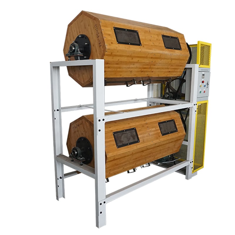
Visual Reference for Process Setup
The image shows a blue vibrating screen with a white background and a logo at the bottom left corner. It appears to be a dust collector, used to separate dust particles from other materials.
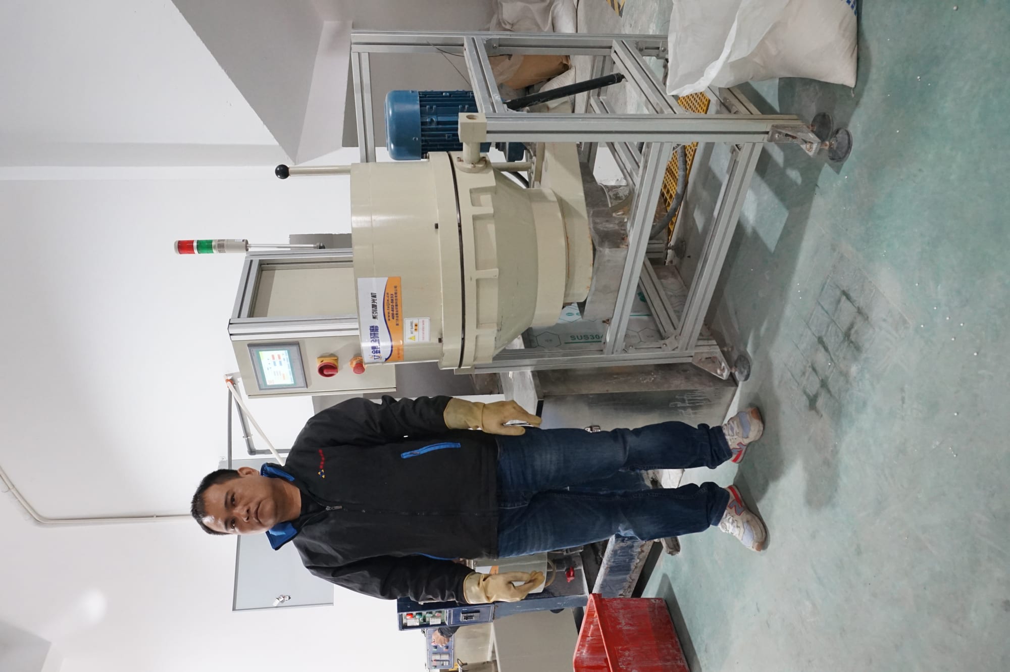
See the Process in Action
Watch how surface finishing equipment processes parts in a real production environment:
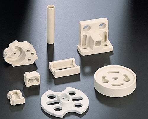
The image shows a set of four green stones on a white surface, which appear to be a stone block and a stone ball. The stones are arranged in a triangular formation, with the stone block in the center
Need to confirm a process before batch production? Send us your part material, photos, dimensions, current surface condition, and target finish. We can help review whether your issue is caused by media, machine settings, compound, water quality, or handling after finishing.
Contact our finishing team →
Related Solutions
These pages may help you compare suitable machines, media, compounds, and processes:
Rotary Barrel Tumbling Ceramic Media Plastic Media Steel Finishing Media Dry Finishing Media
Need Expert Advice for Your Finishing Process?
Send us your part material, photos, dimensions, current surface condition, target finish, and batch quantity. Our team can help recommend suitable finishing machines, media, compounds, and a test process direction for your specific application.
Request process support →


 IPv6 network supported


 +86-592-2381506