How to Remove Burrs from CNC Aluminum Parts Without Edge Damage
May 19 , 2026
CNC Aluminum Deburring Guide
How to Remove Burrs from CNC Aluminum Parts Without Edge Damage
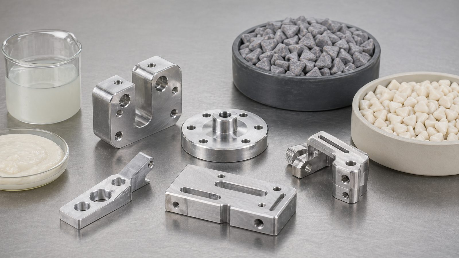
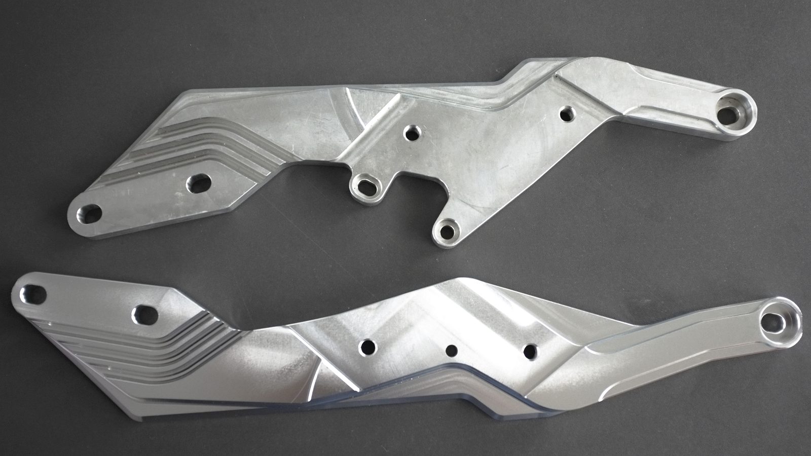
A controlled mass-finishing process can remove light machining burrs, soften tool marks, and prepare aluminum parts for anodizing or coating. The challenge is to remove the burr without rounding functional edges, changing hole geometry, denting the surface, or staining the alloy.
CNC aluminum components often combine cosmetic faces with sealing lands, threads, slots, pockets, and tightly toleranced edges. That makes deburring different from simply making a part look smooth. A successful process must reach the burr while protecting every feature that still has to assemble, seal, locate, or pass inspection.
The best result normally comes from treating the machine, media, compound, water, loading ratio, cycle time, separation, and drying method as one validated recipe. Changing only the abrasive grade rarely solves a process that is damaging edges.
Quick answer: For many damage-sensitive CNC aluminum parts, begin with a small controlled trial using appropriately sized plastic media, an aluminum-compatible compound, enough media to keep parts separated, and short timed inspections. Measure the critical edges before and after each sample. Do not extend the cycle until you know whether useful burr removal is still occurring.
First Define the Burr and the Edge That Must Be Protected
"Remove the burr without edge damage" is not a measurable process target. Before testing, identify the burr source, its location and orientation, and how much edge change is acceptable. A thin drilling burr at a through-hole behaves differently from a folded milling burr along a slot or a heavy breakout burr at an interrupted cut.
Burr condition
Record height, thickness, direction, consistency, and whether it is loose, sharp, folded, or attached to a heavy root.
Protected features
Mark sealing faces, sharp functional corners, threads, small holes, thin walls, engraved details, and datum surfaces.
Acceptance target
Define the permitted edge radius, remaining burr limit, roughness or appearance target, and downstream coating requirement.
Production demand
Record part weight, batch quantity, required pieces per hour, changeover frequency, and acceptable reject rate.
Large or folded burrs should be reduced upstream. If machining creates an inconsistent heavy burr, mass finishing may round the surrounding edge before the burr root is removed. Review tool condition, cutting direction, feeds, speeds, and exit geometry before making the finishing process more aggressive.
Is Mass Finishing the Right Deburring Method?
Mass finishing is well suited to repeatable batch deburring when media can contact the target edges and the parts can move safely. It is especially useful for light burr removal, controlled edge radiusing, removal of fine tool marks, cleaning, and surface preparation before anodizing or coating.
It is less suitable when only one local edge may be touched, the part contains an extremely fragile feature, media cannot reach the burr, or every component must be isolated from contact. Those cases may require brushing, robotic deburring, thermal or electrochemical methods, abrasive flow processing, or fixture-based finishing. The selection should follow the drawing and acceptance criteria, not only the part material.
Choose the Machine According to Part Geometry and Damage Risk
A vibratory finishing machine is a practical starting point for many CNC aluminum batches because the process is observable and can combine finishing, separation, rinsing, and drying. A centrifugal disc finishing machine can deliver a faster, higher-energy action, but its process window may be narrower for delicate parts.
Machine Direction
Where It Fits
Main Risk to Validate
Vibratory bowl
General-purpose batch processing, mixed geometries, and processes that benefit from integrated separation
Part-on-part contact, poor circulation, or media lodging in holes and slots
Vibratory tub
Long or larger components and applications that may use dividers or compartments
Dead zones, part orientation, transfer damage, and separation method
Centrifugal disc
Small to medium parts requiring shorter cycles and stronger cutting action
Rapid edge-radius growth, nesting, contact damage, and heat or foam buildup
For a broader comparison of bowl and tub designs, usable capacity, and line configuration, see our vibratory finishing machine selection guide.
Why Plastic Media Is Often the Starting Point for Aluminum
Plastic-bonded abrasive media has lower density and generally produces a gentler impact than dense ceramic media. That makes plastic finishing media a common starting direction for aluminum, zinc, brass, copper, thin parts, and cosmetic surfaces. It can remove light burrs and machining lines while reducing the risk of deep impingement marks.
This does not mean plastic media is automatically safe or that ceramic media can never be used on aluminum. A hard alloy, robust geometry, or heavier stock-removal target may justify a controlled ceramic-media trial. The result depends on media formulation, size, shape, machine energy, part loading, and cycle time.
Media material controls the general cutting action, while shape and size determine which edges are contacted and whether the media may lodge in holes, slots, or threads.
Media shape and size matter as much as abrasive grade
Match access to the burr. The media must contact the edge without becoming trapped behind a shoulder or inside a pocket.
Avoid dimensional matches. Compare every media dimension with holes, slots, counterbores, threads, and gaps across the media's worn size range.
Check separation early. A recipe is not production-ready if finished parts cannot be separated reliably from the media.
Account for wear. Media becomes smaller during use. A size that is safe when new may later lodge in an opening or pass through a separation screen.
Prevent Part-on-Part Contact and Cosmetic Damage
Aluminum surfaces can pick up dents and witness marks when parts collide. The media must do more than cut the burr: it also separates and cushions the workpieces. The correct media-to-parts ratio cannot be selected from chamber volume alone because part weight, geometry, nesting behavior, and cosmetic sensitivity all change the contact risk.
Begin with a small number of marked parts and enough media to keep them separated during the complete circulation path.
Observe loading, steady-state movement, separation, discharge, and transfer to the dryer.
Inspect broad faces and corners under side lighting for new contact marks.
Increase the part load step by step only after the previous level passes inspection.
Define production capacity as accepted parts per cycle, not the maximum amount that physically fits in the chamber.
Use Compound and Water to Control Cleaning, Staining, and Cutting
The liquid system carries removed metal and abrasive fines away, keeps media clean, helps control foam, and influences the final surface. Select an aluminum-compatible finishing compound and follow its recommended starting concentration. More compound is not automatically better; overdosing can increase foam or leave residue, while insufficient cleaning can allow fines to redeposit.
Use a repeatable dosing method and record water flow, concentration, temperature, and solution condition.
Check whether the selected chemistry is compatible with the specific aluminum alloy and the next operation.
Keep the bowl, drains, tank, screens, and media free of chips from previous jobs.
Rinse completely and begin drying promptly to reduce water spots and oxidation marks.
Inspect blind holes and pockets where dirty liquid may remain after separation.
Build the Recipe with Short, Measured Trials
The safest way to protect a critical edge is to measure progress over time. Use parts from the same machining condition, preserve an untreated control, and change only one variable in each test. Short timed samples reveal whether the burr is being removed before excessive radiusing begins.
1. Record the baseline
Photograph and measure burrs, functional edges, critical dimensions, and surface condition.
2. Establish safe movement
Confirm circulation, media coverage, part separation, and absence of nesting or lodging.
3. Sample by time
Remove marked parts at fixed intervals, then rinse and dry them completely.
4. Measure the edge
Compare remaining burr, edge radius, roughness, appearance, and critical dimensions.
5. Adjust one variable
Change media, time, compound, flow, machine energy, or loading - not several at once.
6. Confirm at production load
Repeat the approved recipe with the intended batch size and complete post-process route.
Troubleshooting CNC Aluminum Deburring Defects
Observed Result
Likely Cause
Controlled Test
Burr remains but edge radius grows
Media cannot reach the burr root, burr is too heavy, or machining created a folded burr
Review upstream machining and test a shape that reaches the burr without matching nearby openings
Dents or random contact marks
Part-on-part collision, insufficient cushioning, overload, or damage at transfer points
Reduce the part count and increase media coverage while keeping other settings unchanged
Deep scratches
Metal-chip contamination, broken or mixed media, or an overly aggressive recipe
Clean the full system and run a known reference part with clean media
Gray film, smut, or staining
Incompatible chemistry, overloaded solution, poor rinsing, unsuitable water, or delayed drying
Prepare fresh solution at the recommended concentration, add a clean rinse, and dry immediately
Media stuck in holes or slots
Media dimension matches a feature now or after wear
Test a non-lodging shape or size and verify the complete separation route
Inconsistent parts within one batch
Unstable circulation, mixed starting surfaces, nesting, or uneven liquid distribution
Run a smaller sorted batch and observe movement in every area of the chamber
Prepare the Surface for Anodizing, Coating, or Assembly
A deburred part is not automatically ready for the next process. Mass finishing changes the surface texture and may leave abrasive fines, compound residue, or retained liquid. If the part will be anodized, plated, painted, bonded, sealed, or assembled, confirm cleanliness and surface condition with the downstream supplier or internal process owner.
Keep accepted samples from both before and after the downstream process. A surface that looks uniform before anodizing may reveal alloy or machining differences after color development, so the complete route - not only the deburring step - must be validated.
Information Needed for a Reliable Process Trial
Aluminum alloy and temper, part drawing, dimensions, weight, and annual or daily quantity
Photos of the incoming burr and the exact edges that must remain protected
Maximum acceptable edge radius, dimensional tolerances, and cosmetic standard
Hole, slot, pocket, thread, and internal-feature dimensions relevant to media lodging
Required final roughness or visual finish and the next operation, such as anodizing or coating
Current equipment, media, compound, cycle time, defects, and target production rate
Need a deburring process for CNC aluminum parts? Send part photos, the alloy, dimensions, burr location, protected edges, target finish, and batch quantity. We can recommend a machine, media, compound, and controlled trial direction.
Request a process evaluation ->
Frequently Asked Questions
What media is best for deburring CNC aluminum parts?
Plastic abrasive media is often the first trial direction because its lower density provides a gentler action on aluminum and cosmetic surfaces. The correct grade, shape, and size still depend on the burr, protected features, target finish, machine, and lodging risk.
Can ceramic media be used on aluminum?
Yes, in some applications. Ceramic media may provide faster cutting, but its higher density can increase surface marking and edge-radius growth. Use a controlled trial and measure critical features rather than selecting media by material name alone.
How do I prevent sharp edges from becoming too rounded?
Start with short timed samples, gentler media, safe machine motion, and a measurable edge-radius limit. If the burr remains while the surrounding edge keeps rounding, improve burr access or reduce the burr during machining instead of simply extending the finishing cycle.
Why do aluminum parts turn gray or develop stains after tumbling?
Possible causes include incompatible chemistry, dirty solution, metal-fine redeposition, unsuitable water, incomplete rinsing, retained liquid, or delayed drying. Test fresh aluminum-compatible solution, a clean rinse, and immediate drying while holding mechanical settings constant.
Will vibratory finishing remove machining lines?
It can reduce light tool marks and create a more uniform texture, but the required stock removal may also change dimensions and edge radii. Deep cutter marks should be addressed in machining or evaluated with a staged finishing process.
How long should CNC aluminum parts be tumbled?
There is no universal cycle time. It depends on alloy, burr size, part geometry, media, compound, machine energy, load, and acceptance target. Establish the shortest repeatable cycle through timed samples and dimensional inspection.
Related Equipment and Process Resources
Vibratory Finishing Machines Centrifugal Disc Finishers Plastic Finishing Media Finishing Compounds Machine Selection Guide Contact the Finishing Team
Protect the Edge by Controlling the Complete Recipe
Reliable aluminum deburring comes from matching burr access, media, machine motion, cushioning, chemistry, time, and inspection. Validate the process on marked samples, measure critical edges, and confirm the final recipe at production load.
Send your CNC aluminum parts for process evaluation ->
Related business: jingseyewear


 IPv6 network supported


 +86-592-2381506