• How to Deburr Plastic and Rubber Parts: Mass Finishing, Media, and Process Limits
    How to Deburr Plastic and Rubber Parts: Mass Finishing, Media, and Process Limits Jul 16 , 2026
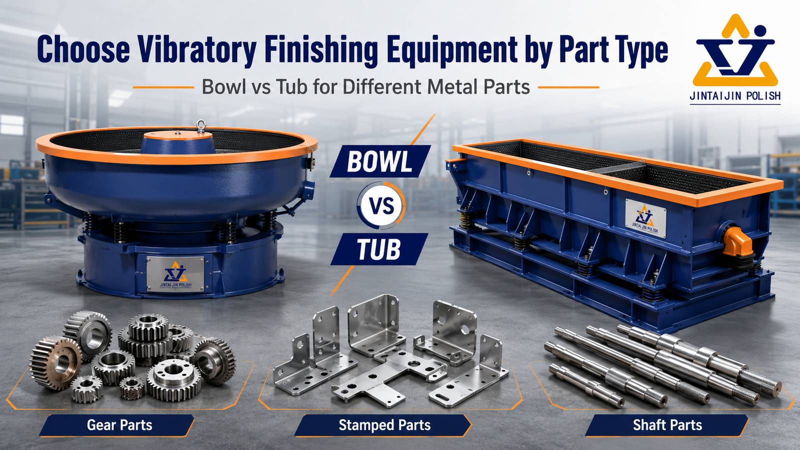
    Plastic and Rubber Part Finishing Guide How to Deburr Plastic and Rubber Parts: Mass Finishing, Media, and Process Limits Flash, gate marks, machining burrs, and rough build lines do not all respond to the same finishing method. This guide explains when mass finishing is a practical option for plastic and rubber parts, how to select equipment and media, and when trimming, blasting, or cryogenic deflashing is the safer route. Plastic and rubber components can leave the mold, machining center, or additive manufacturing process with several different defects. A thin parting-line flash may break away easily, while a heavy gate vestige may need controlled cutting. A flexible rubber lip can bend away from abrasive media instead of being removed. Transparent or highly cosmetic plastic parts may lose clarity before the unwanted edge is gone. For that reason, equipment selection should not begin with the question, “Which machine removes plastic flash?” It should begin with the material, defect, geometry, tolerance, surface requirement, and acceptable contact between parts. Mass finishing can process many components efficiently, but only after a small trial confirms that the defect is removable without rounding functional features, lodging media, or creating haze. Quick answer: Mass finishing is most suitable for small and medium plastic or rubber parts with light flash, fine machining burrs, rough build lines, or surfaces that need controlled smoothing. Heavy gates, very soft flexible flash, critical sealing lips, deep internal features, and highly sensitive optical surfaces may require trimming, blasting, cryogenic deflashing, or a combined process instead. First Identify What Must Be Removed The word “burr” is often used for several different conditions. Correctly naming the defect prevents an aggressive process from being applied to the wrong problem. Defect Typical Origin Mass Finishing Potential Main Risk Thin parting-line flash Injection, compression, or transfer molding Often suitable when the flash is thin enough to break away Flexible flash may fold instead of cutting Gate vestige Runner or gate separation Suitable only for small residual marks after primary gate removal Long cycles can dish or round the surrounding surface Machining burr Drilling, milling, turning, or routing engineering plastics Good candidate when edges are accessible to media Critical holes, threads, and sealing edges may change Layer or support mark FDM, SLA, SLS, or other additive processes Useful for controlled smoothing after supports are removed Fine details and thin walls can be softened Rubber molding flash O-rings, seals, gaskets, and molded elastomer parts Possible when the flash becomes brittle or can be mechanically separated Functional lips and soft edges can deform or remain unfinished When Mass Finishing Is a Good Fit A vibratory, barrel, or centrifugal process is most useful when many parts can move freely with media and the unwanted material is smaller or weaker than the features that must remain. Suitable jobs commonly share these characteristics: Parts are small enough to process as a controlled batch. The burr or flash is light and accessible from the outside. Media contact is acceptable on the visible and functional surfaces. Edges may be lightly rounded without changing assembly performance. Parts can be separated from the media without lodging or manual picking. The process target is repeatable deburring, smoothing, cleaning, or preparation for a later coating or polishing step. Engineering plastics such as ABS, nylon, acetal, polycarbonate, and PEEK can behave very differently even when the parts have similar geometry. Resin grade, fillers, moisture, wall thickness, molded stress, and starting surface all affect the result. The material name alone is not enough to define a recipe. When Another Deflashing Method Is Safer Mass finishing should not be forced onto every molded part. Use another primary removal method, or combine processes, when one of the following conditions is present: Heavy gates or runners: clip, trim, mill, or cut the bulk material before surface finishing. Very soft flash: flexible elastomer flash may require cryogenic deflashing or another process that makes the excess material easier to separate. Critical sealing lips: O-rings, diaphragms, and seals require validation of profile, dimensions, and leakage performance after processing. Deep blind features: media cannot remove material it cannot contact, and trapped media may create a larger production problem. Optical or transparent surfaces: haze and fine scratches may appear before the defect is removed. A dedicated, staged process is required. Very thin or flexible parts: parts may overlap, nest, or distort instead of moving independently. Choose the Machine by Part Behavior Process Useful For What to Validate Vibratory bowl General batch deburring and smoothing of small molded or machined parts Part circulation, part-on-part contact, separation screen, and media lodging Vibratory tub Long, flat, or awkward parts that do not circulate well in a bowl Part orientation, chamber dividers, and contact between long parts Barrel finishing Gentler rolling action and staged dry or wet polishing Cycle time, loading density, heat, and uniform exposure Centrifugal disc Shorter, higher-energy cycles for robust small parts Impact, edge loss, heat generation, and part entanglement For a broader comparison of bowl, tub, capacity, and workflow decisions, see our vibratory finishing machine selection guide. The same geometry-first method applies, but plastic and rubber parts generally require stricter control of heat, contact, and dimensional change. Media Selection: Gentle Does Not Mean Ineffective Media must be aggressive enough to act on the defect while remaining safe for the base material. Lower-density plastic finishing media is often evaluated for damage-sensitive parts because it can provide controlled cutting with less impact than dense ceramic media. Shape is as important as material: cones, pyramids, triangles, cylinders, and specialty shapes contact edges differently and separate differently from holes and slots. Never select media only from the outside dimensions of the part. Measure through-holes, blind holes, slots, lens grooves, undercuts, and gaps between ribs. A media shape that can enter a feature may rotate and lock inside it. The safest starting point is a lodging test with a small sample of every part variant. The compound or process liquid also affects lubrication, cleaning, heat control, foam, residue, and how removed material leaves the working chamber. Transparent and cosmetic parts should be inspected after washing and drying, not only while wet, because water can temporarily hide fine scratches or haze. Rubber sealing parts require more than a visual check. After deflashing, inspect the sealing profile, dimensions, surface damage, and functional performance. A Safe Process Development Workflow Define the defect. Record flash thickness, gate height, burr location, surface marks, and any features that must remain sharp. Record the material. Include the exact resin or elastomer grade, fillers, hardness where relevant, color, and whether the part is transparent or plated later. Remove bulk material first. Do not use a long finishing cycle to replace gate cutting or heavy trimming. Perform a media lodging test. Check every hole, slot, groove, undercut, and nested geometry before running a full batch. Start with a small controlled load. Keep reference parts from the untreated batch and change one variable at a time. Inspect at short intervals. Track defect removal, edge radius, dimensions, gloss, color, temperature, and new contact marks. Validate separation and cleaning. Confirm that media, dust, compound, and loose flash can be removed consistently. Repeat the approved recipe. Validate more than one batch before scaling to production volume. Common Problems and Corrective Direction Observed Result Likely Direction to Check Flash bends but remains attached The flash may be too flexible for the current mechanical action; compare trimming, blasting, or cryogenic deflashing. Edges round before the gate mark disappears Remove more of the gate before finishing, shorten the cycle, or reduce media aggressiveness. White haze or fine scratches appear Check media condition, contamination, dry friction, heat, compound, and part-on-part contact. Parts stick, nest, or finish unevenly Reduce loading density, change media-to-part volume, use dividers, or select a different chamber motion. Media remains in holes or grooves Change media size or shape and repeat the lodging test before production. If a batch develops scratches, residue, dents, or uneven results, use a controlled one-variable method rather than increasing time immediately. Our vibratory finishing troubleshooting guide provides a structured diagnostic workflow. Information to Send for a Process Trial A useful process recommendation requires more than a part photo. Send the following information with representative untreated samples whenever possible: Exact material or resin/elastomer grade and any fillers; Part dimensions, weight, wall thickness, and critical tolerances; Close-up photos of flash, gates, burrs, layer lines, and protected features; Current removal method and the reason it must be improved; Target edge, surface appearance, cleanliness, and downstream process; Batch quantity, daily volume, acceptable cycle time, and separation method; Inspection method, especially for sealing, optical, mating, or plated surfaces. Frequently Asked Questions Can vibratory finishing remove injection molding flash? It can remove light, accessible flash from suitable materials and geometries. Heavy gates should be removed first, and flexible flash may need a different method. A sample trial is necessary. Can rubber O-rings be deflashed in a mass finishing machine? Some rubber parts can be mechanically deflashed, but soft flash and functional sealing profiles require special care. Cryogenic deflashing may be more appropriate for certain elastomers. Always validate dimensions and sealing performance after processing. Which media is safest for plastic parts? There is no universal safest media. The correct choice depends on resin grade, defect, surface requirement, geometry, and the risk of media lodging. Lower-density plastic media is often evaluated first for damage-sensitive parts, but only testing can confirm the result. Why do transparent plastic parts become cloudy after finishing? Common causes include aggressive media, contaminated media, excessive friction or heat, part-on-part contact, residue, and an unsuitable drying method. See our guide to polishing acrylic parts without haze or edge burn. Should the full production batch be tested first? No. Begin with representative samples and keep untreated references. Confirm defect removal, dimensional stability, appearance, cleaning, separation, and functional performance before increasing the load. Related Equipment and Process Resources Vibratory Finishing Machines Barrel Finishing Machines Disc Finishing Machines Plastic Finishing Media Pre-Polishing Media for Plastic Test the Part Before Selecting the Process Send your material grade, part photos, dimensions, defect close-ups, protected features, target finish, and batch quantity. Our team can help compare mass finishing with other deflashing routes and define a controlled sample test. Request a plastic or rubber part finishing trial →
  • How to Prevent Tumbling Media from Lodging in Holes Slots and Threads
    How to Prevent Tumbling Media from Lodging in Holes Slots and Threads May 28 , 2026
    Process Troubleshooting How to Prevent Tumbling Media from Lodging in Holes Slots and Threads Surface finishing defects are often caused by interactions between multiple process variables rather than a single root cause. A systematic approach to identifying the actual problem reduces wasted time, media, and compound, and leads to faster process correction. When surface defects appear after finishing, the cause is rarely a single variable. Most finishing problems result from interactions between media condition, machine settings, compound concentration, water quality, and part loading. A systematic diagnostic approach — checking variables in order of likelihood — solves problems faster than trial-and-error adjustments. Quick answer: Start by documenting the defect precisely. Take photos under consistent lighting. Note when in the cycle the defect appears, which parts are affected, and whether the symptom is consistent across the batch or random. This information narrows the root cause to a specific process variable and avoids wasted adjustments. Diagnostic Table: Match the Symptom to the Root Cause Symptom Likely Cause What to Check Recommended Adjustment Surface finish is inconsistent across the batch Uneven media distribution or part-on-part contact Media-to-part ratio, machine loading, compound flow Adjust ratio, reduce batch size, or add cushion media Parts show unexpected scratches or surface marks Contaminated media, wrong media shape, or overly aggressive cycle Check media cleanliness, separation, and storage bins for mixed materials Clean or replace media, test a gentler media shape or smaller size Edges are rounded or functional details are lost Over-processing or media too large for part features Measure critical dimensions before and after test cycles Shorten cycle time, use smaller media, reduce machine speed or amplitude Surface residue or film is visible after drying Dirty compound, poor water quality, or incomplete rinsing Water quality, compound concentration, rinsing and drying sequence Use clean water, refresh compound at proper intervals, improve drying process Brightness varies significantly between parts Mixed surface starting conditions or uneven processing Incoming part surface, batch sorting, media distribution Sort parts by starting condition, run separate batches for different surface states Step-by-Step Diagnosis Workflow Follow these steps in order. Most defects are caused by the first three variables — stopping there saves time: Check media condition first. Worn, contaminated, or incorrectly sized media causes more defects than any other variable. Media should be clean, well-sorted, and sized at least 1.5x the largest cavity dimension. Verify compound concentration and flow. Too little compound reduces cutting action. Too much creates excess foam and residue. Check the compound pump, nozzle position, and dilution ratio. Inspect water quality. Hard water, high chlorine, or recycled water that has not been filtered can cause staining, spotting, and inconsistent brightening. Review machine settings. Speed, amplitude, and cycle time interact with the media and compound. A machine running at full speed may be too aggressive for fine finishing. Check part loading and separation. Overloaded machines cause part-on-part damage. Underloaded machines waste energy and extend cycle time. Common Mistakes When Diagnosing Finishing Problems Only extending cycle time. Longer time can increase heat, edge rounding, and part-on-part damage if the root cause is media or compound. Switching to more aggressive media immediately. A smaller media size or different shape often solves the problem without risking surface damage. Ignoring media cleanliness. Dirty media, mixed media types, or metal fines in the bowl can scratch parts that should be getting polished. Skipping test cycles. Always run a small sample batch first to confirm the process before committing full production volume. Overloading the machine. Too many parts in one batch can cause impact damage, uneven finishing, and longer cycle times. Judging parts while wet. Water film can hide scratches and residue until drying reveals them. Inspect after drying under proper light. Visual Reference for Process Setup The image shows a blue vibrating screen with a white background and a logo at the bottom left corner. It appears to be a dust collector, used to separate dust particles from other materials. See the Process in Action Watch how surface finishing equipment processes parts in a real production environment: The image shows a set of four green stones on a white surface, which appear to be a stone block and a stone ball. The stones are arranged in a triangular formation, with the stone block in the center Need to confirm a process before batch production? Send us your part material, photos, dimensions, current surface condition, and target finish. We can help review whether your issue is caused by media, machine settings, compound, water quality, or handling after finishing. Contact our finishing team → Related Solutions These pages may help you compare suitable machines, media, compounds, and processes: Rotary Barrel Tumbling Ceramic Media Plastic Media Steel Finishing Media Dry Finishing Media Need Expert Advice for Your Finishing Process? Send us your part material, photos, dimensions, current surface condition, target finish, and batch quantity. Our team can help recommend suitable finishing machines, media, compounds, and a test process direction for your specific application. Request process support →
  • Why Stainless Steel Parts Are Not Bright After Tumbling and How to Improve the Finish
    Why Stainless Steel Parts Are Not Bright After Tumbling and How to Improve the Finish May 28 , 2026
    Process Troubleshooting Why Stainless Steel Parts Are Not Bright After Tumbling and How to Improve the Finish Surface finishing defects are often caused by interactions between multiple process variables rather than a single root cause. A systematic approach to identifying the actual problem reduces wasted time, media, and compound, and leads to faster process correction. When surface defects appear after finishing, the cause is rarely a single variable. Most finishing problems result from interactions between media condition, machine settings, compound concentration, water quality, and part loading. A systematic diagnostic approach — checking variables in order of likelihood — solves problems faster than trial-and-error adjustments. Quick answer: Start by documenting the defect precisely. Take photos under consistent lighting. Note when in the cycle the defect appears, which parts are affected, and whether the symptom is consistent across the batch or random. This information narrows the root cause to a specific process variable and avoids wasted adjustments. Diagnostic Table: Match the Symptom to the Root Cause Symptom Likely Cause What to Check Recommended Adjustment Surface finish is inconsistent across the batch Uneven media distribution or part-on-part contact Media-to-part ratio, machine loading, compound flow Adjust ratio, reduce batch size, or add cushion media Parts show unexpected scratches or surface marks Contaminated media, wrong media shape, or overly aggressive cycle Check media cleanliness, separation, and storage bins for mixed materials Clean or replace media, test a gentler media shape or smaller size Edges are rounded or functional details are lost Over-processing or media too large for part features Measure critical dimensions before and after test cycles Shorten cycle time, use smaller media, reduce machine speed or amplitude Surface residue or film is visible after drying Dirty compound, poor water quality, or incomplete rinsing Water quality, compound concentration, rinsing and drying sequence Use clean water, refresh compound at proper intervals, improve drying process Brightness varies significantly between parts Mixed surface starting conditions or uneven processing Incoming part surface, batch sorting, media distribution Sort parts by starting condition, run separate batches for different surface states Step-by-Step Diagnosis Workflow Follow these steps in order. Most defects are caused by the first three variables — stopping there saves time: Check media condition first. Worn, contaminated, or incorrectly sized media causes more defects than any other variable. Media should be clean, well-sorted, and sized at least 1.5x the largest cavity dimension. Verify compound concentration and flow. Too little compound reduces cutting action. Too much creates excess foam and residue. Check the compound pump, nozzle position, and dilution ratio. Inspect water quality. Hard water, high chlorine, or recycled water that has not been filtered can cause staining, spotting, and inconsistent brightening. Review machine settings. Speed, amplitude, and cycle time interact with the media and compound. A machine running at full speed may be too aggressive for fine finishing. Check part loading and separation. Overloaded machines cause part-on-part damage. Underloaded machines waste energy and extend cycle time. Common Mistakes When Diagnosing Finishing Problems Only extending cycle time. Longer time can increase heat, edge rounding, and part-on-part damage if the root cause is media or compound. Switching to more aggressive media immediately. A smaller media size or different shape often solves the problem without risking surface damage. Ignoring media cleanliness. Dirty media, mixed media types, or metal fines in the bowl can scratch parts that should be getting polished. Skipping test cycles. Always run a small sample batch first to confirm the process before committing full production volume. Overloading the machine. Too many parts in one batch can cause impact damage, uneven finishing, and longer cycle times. Judging parts while wet. Water film can hide scratches and residue until drying reveals them. Inspect after drying under proper light. Visual Reference for Process Setup The image shows a pair of metal parts on a gray surface, which appear to be part of a high-quality aluminum die casting machine. The metal parts are silver in color and have a glossy finish. See the Process in Action Watch how surface finishing equipment processes parts in a real production environment: The image shows a pair of metal parts on a gray background, which appear to be part of a CNC milling machine. The metal parts are silver in color and have a glossy finish. Need to confirm a process before batch production? Send us your part material, photos, dimensions, current surface condition, and target finish. We can help review whether your issue is caused by media, machine settings, compound, water quality, or handling after finishing. Contact our finishing team → Related Solutions These pages may help you compare suitable machines, media, compounds, and processes: Steel Finishing Media Vibratory Finishing Machine Grinding Finishing Machine Disc Finishing Machines Barrel Finishing Machines Rotary Barrel Tumbling Need Expert Advice for Your Finishing Process? Send us your part material, photos, dimensions, current surface condition, target finish, and batch quantity. Our team can help recommend suitable finishing machines, media, compounds, and a test process direction for your specific application. Request process support →
  • How to Prevent Water Spots, White Film, and Cloudy Stainless Steel After Tumbling
    How to Prevent Water Spots, White Film, and Cloudy Stainless Steel After Tumbling May 28 , 2026
    Wet Finishing Troubleshooting How to Prevent Water Spots, White Film, and Cloudy Stainless Steel After Tumbling A stainless steel part can look clean while wet and develop spots, haze, streaks, or a chalky film only after drying. This guide separates surface-finish problems from rinsing, compound, water-quality, and drying problems so the process can be corrected without unnecessarily extending the tumbling cycle. Water spots and white residue after wet mass finishing are often treated as polishing failures. Operators may add more compound, increase cycle time, or change media even though the unwanted mark formed after the cutting or burnishing stage. This can make the finish less consistent while leaving the actual rinse-and-dry problem unchanged. The first diagnostic question is simple: does the mark exist before the part dries? Inspect a cleaned part under consistent light while wet, after the final rinse, and again after complete drying. If the surface is uniform before drying but spotted afterward, investigate dissolved minerals, carried-over compound, rinse quality, drainage, handling, and drying conditions before changing the main finishing recipe. Quick answer: White spots are commonly associated with mineral deposits or dried process residue. A cloudy film can also come from excessive or degraded compound, contaminated rinse water, incomplete drainage, or redeposition of fine metal and media solids. Confirm the defect stage, run a clean-water comparison, and change one variable at a time. Identify the Mark Before Changing the Process Observed Condition Useful First Check Possible Direction Round spots with visible edges Compare normal water with known low-mineral rinse water Mineral concentration as droplets evaporate Uniform chalky or milky film Wipe a dried reference area and inspect rinse clarity Compound carryover, suspended solids, or insufficient rinsing Streaks running from holes or recesses Observe drainage orientation and liquid trapped in features Slow drainage or contaminated liquid leaving cavities during drying Dark or colored staining Check chemistry, mixed-metal contamination, time delay, and corrosion history Chemical reaction or contamination; specialist review may be required Fine haze that does not wipe away Inspect under magnification before and after finishing Micro-scratching or surface texture rather than removable residue A wipe test is useful but not conclusive. If a mark transfers to a clean lint-free cloth, residue is likely involved. If it remains, the cause may be mineral scale, staining, or a change in surface texture. Avoid applying an unknown cleaner to production parts; it can hide evidence or react with the surface. Separate Finishing, Rinsing, and Drying Collect several parts from the same batch and divide them immediately after finishing. Process the reference groups through different controlled finishing steps while keeping the main tumbling recipe unchanged: Reference A: normal plant rinse and normal drying. Reference B: fresh final rinse using known clean, lower-mineral water, followed by the same drying method. Reference C: the normal rinse followed by improved drainage and a clean drying environment. Untreated reference: an incoming part kept for surface and stain comparison. If only Reference B improves, water quality or rinse contamination deserves priority. If Reference C improves, drainage or drying is more likely. If all finished parts show the same non-removable haze before drying, return to the media, part contact, and cycle conditions. This small split test is usually more informative than changing several production settings at once. Check Water Quality and Rinse Control Water that appears clear can still contain dissolved minerals. As droplets evaporate, dissolved material remains on the surface. Recycled rinse water can also accumulate compound, metal fines, abrasive debris, oil, and cleaning by-products. The acceptable water condition depends on the alloy, finish requirement, chemistry, and inspection standard, so a universal hardness or conductivity limit should not be assumed. Record the water source, conductivity or other available plant water measurements, and whether the result changes by shift or season. Inspect rinse tanks, spray nozzles, filters, transfer baskets, and pipes for accumulated solids or biofilm. Confirm that the final rinse is not simply redistributing contaminated liquid from earlier stages. Use a controlled comparison with fresh water before investing in treatment equipment. Do not mix chemistry or discharge streams without checking the compound supplier's instructions and local environmental requirements. Review Compound Concentration and Carryover A mass-finishing compound can support cleaning, lubrication, soil suspension, foam control, and corrosion management. More compound is not automatically better. Overdosing may increase foam and leave more material to rinse away, while underdosing can reduce cleaning and allow removed solids to redeposit. A degraded bath can behave differently from a fresh mixture even when the nominal concentration is unchanged. Verify the dosing method, pump performance, nozzle position, make-up water, bath age, and actual concentration using the supplier's recommended control method. Inspect whether foam or dirty liquid travels with parts into the rinse. If chemistry is suspected, compare a small batch using a freshly prepared, documented mixture rather than adding an unmeasured amount to the existing tank. See our finishing compounds range for the role of process chemistry in cleaning and surface finishing. Improve Drainage and Drying Without Creating New Marks The final rinse can be clean and still leave marks if liquid remains in holes, recesses, overlapping parts, or baskets. During drying, this trapped liquid may travel across an already dry surface and leave a streak. Parts that nest or touch can also shield water and create uneven drying. Drain consistently: define part orientation and drainage time before parts enter the dryer. Avoid dirty handling: inspect gloves, baskets, screens, trays, and conveyors for oil or dried chemistry. Control loading: separate parts that overlap, nest, or trap water. Keep drying media clean: contaminated absorbent media can transfer residue back to the part. Validate temperature: faster is not always cleaner. Excessive heat can dry contaminated droplets rapidly and make deposits more visible. Where appropriate, compare centrifugal drying, hot-air drying, and absorbent-media drying using representative parts. Our drying equipment pages provide examples of post-finishing systems, but the correct method still depends on geometry, cleanliness target, throughput, and downstream handling. When the Problem Is Actually the Surface Finish Not every cloudy appearance is removable residue. Fine scratches, excessive cutting, worn media, mixed media, part-on-part contact, and inconsistent incoming surfaces can scatter light and look like a film. Examine the part dry under repeatable lighting and magnification. If the haze follows contact areas, remains after controlled cleaning, or is already visible before the rinse stage, investigate the finishing process. For insufficient brightness and burnishing decisions, use the separate guide Why Stainless Steel Parts Are Not Bright After Tumbling. For scratches, dents, residue, and uneven results across different materials, follow our broader vibratory finishing troubleshooting workflow. Controlled Corrective-Action Checklist Photograph the mark under fixed lighting before wiping or reprocessing. Record when the defect first becomes visible: after tumbling, after rinse, or after drying. Keep untreated and normally processed reference parts. Run a fresh-water final-rinse comparison on a small sample. Check compound dosing, bath condition, foam, suspended solids, and rinse carryover. Inspect baskets, gloves, trays, nozzles, filters, and drying media. Change only one controlled variable per comparison. Approve the corrected process only after repeated batches meet the same dry inspection standard. Frequently Asked Questions Why do stainless steel parts look clean when wet but spotted after drying? A water film can hide fine residue and surface variation. As droplets evaporate, dissolved minerals or process residues become concentrated and visible. Compare a fresh final rinse and a controlled drying method before changing the tumbling cycle. Should more polishing compound remove the white film? Not necessarily. Additional compound can increase carryover or foam if the existing problem is overdosing, bath contamination, or insufficient rinsing. Measure and control the mixture according to the supplier's process instructions. Can steel media improve brightness without fixing water spots? Steel media can be evaluated for burnishing suitable parts, but it does not replace clean rinsing and drying. A brighter surface may make spots more visible. Confirm geometry, media lodging, part contact, and separation before using steel finishing media. When should a laboratory or chemistry specialist be involved? Seek specialist support when marks are colored, corrosive, difficult to identify, associated with a regulated cleanliness requirement, or potentially related to alloy condition, passivation, chemical attack, or cross-contamination. Do not assume every stain is a simple drying deposit. Related Process Resources Vibratory Finishing Machines Finishing Compounds Steel Finishing Media Dryers Need Help Isolating a Wet-Finishing Defect? Send the stainless steel grade, starting condition, process stages, media, compound, water source, rinse method, drying method, defect photos, part geometry, and batch quantity. We can help define a controlled comparison and equipment direction without assuming that every spot requires a longer polishing cycle. Request process support →
  • Vibratory Finishing vs Barrel Tumbling Which Process Fits Your Parts
    Vibratory Finishing vs Barrel Tumbling Which Process Fits Your Parts May 28 , 2026
    Process Comparison Vibratory Finishing vs Barrel Tumbling Which Process Fits Your Parts Choosing between two finishing processes requires understanding how each method applies energy to the media, how the media contacts the part, and how the process variables scale with batch size and production rate. This comparison covers the key differences to help you decide which process matches your production needs. When comparing two finishing processes, the decision often comes down to four variables: cycle time, surface result, part suitability, and operating cost. No single process works best for every part geometry, material, or production volume. The right choice depends on understanding how each process applies energy to the media and how that energy transfers to the part surface. Quick answer: Compare the two processes based on your part material, geometry, surface target, and batch size. The table below shows the key differences. For most metal parts needing moderate deburring and uniform finish within 30-60 minutes, vibratory finishing is the more versatile choice. For delicate parts, small batches, or gentle action, barrel tumbling still has clear advantages. Side-by-Side Process Comparison Factor Process A Process B Which to Choose Cycle Time 15-60 min 2-12 hours Process A for speed; Process B for gentleness Surface Uniformity Good across batch Very good — consistent contact Process B for delicate features Edge Control Moderate — can round edges Excellent — minimal edge rounding Process B for tight tolerances Media Compatibility All media types Small media only Process A for versatility Operating Cost Medium Low Process B for budget Batch Size Medium to large Small to medium Process A for volume Automation Easy to automate Manual handling common Process A for production lines How Process Selection Affects Media and Compound Choice The process type determines what size, shape, and material of media can be used effectively. It also limits the type of compound action — wet compounds require recirculation and drainage, while dry compounds need dust collection. Consider both the media type and the compound delivery system when choosing between processes. Match media size to the process's motion intensity: faster processes need tougher media that resists breakage. Consider whether wet or dry compound delivery is available for each process type. Test sample parts before committing to one process — surface results can differ significantly even with the same media. Common Mistakes When Choosing Between Processes Choosing based only on cycle time. A faster process that damages delicate features is not worth the speed. Verify surface quality at the same time as cycle time. Assuming the process that works for one material works for another. Aluminum, stainless steel, brass, and plastic can all require different processes even for the same surface target. Not accounting for post-process handling. A fast process that generates heat or compound residue may require additional rinsing, drying, or inspection steps that cancel the time savings. Skipping a sample test with actual parts. Brochure specifications do not predict real results. Always send parts for a test run before purchasing equipment. Visual Reference for Process Setup The image shows a group of aluminum parts on a black surface, which appear to be die-cast aluminum parts. The parts are arranged in a neat and orderly fashion, with some of them overlapping each other See the Process in Action Watch how surface finishing equipment processes parts in a real production environment: The image shows a white and green vibrating screen with a logo at the bottom left corner. It is a centrifugal fan, which is used to circulate air throughout a variety of materials. Need to confirm a process before batch production? Send us your part material, photos, dimensions, current surface condition, and target finish. We can help review whether your issue is caused by media, machine settings, compound, water quality, or handling after finishing. Contact our finishing team → Related Solutions These pages may help you compare suitable machines, media, compounds, and processes: Vibratory Finishing Machine Barrel Finishing Machines Rotary Barrel Tumbling Grinding Finishing Machine Disc Finishing Machines Magnetic Finishing Machines Need Expert Advice for Your Finishing Process? Send us your part material, photos, dimensions, current surface condition, target finish, and batch quantity. Our team can help recommend suitable finishing machines, media, compounds, and a test process direction for your specific application. Request process support →
  • Magnetic Finishing Machine Guide for Deburring Small Metal Components
    Magnetic Finishing Machine Guide for Deburring Small Metal Components May 27 , 2026
    Surface Finishing Magnetic Finishing Machine Guide for Deburring Small Metal Components This guide covers the key factors to consider when planning a surface finishing process for your parts. Material, geometry, batch size, and target surface quality all influence the choice of equipment, media, compound, and process parameters. This guide is based on common surface finishing scenarios observed across production facilities. The recommendations here apply to typical metal and plastic parts processed in vibratory finishing, barrel tumbling, disc finishing, and related mass finishing equipment. Specific results vary by material, part geometry, equipment condition, and operator technique. Quick answer: Start by identifying your part material, incoming surface condition, and target finish. Select media, compound, and machine settings that match these three inputs. Test a small sample batch first. Adjust incrementally based on measured results rather than assumptions. Key Process Variables to Consider Every finishing process has five primary variables that control the outcome. Understanding how they interact is the foundation of consistent quality: Media type, size, and condition: determines the cutting or polishing action on the part surface. Compound chemistry and concentration: controls cutting speed, surface finish, cleaning, and corrosion protection. Machine motion (speed, amplitude, vibration pattern): affects how media contacts the part and how energy is transferred. Water quality and flow (for wet processes): carries compound, removes debris, and affects chemical reaction rates. Part loading density and separation: determines whether parts contact each other and how uniformly media reaches all surfaces. Common Mistakes to Avoid Changing multiple variables at once. When a defect appears, change only one variable at a time. Document the result before making another adjustment. Changing media, compound, and machine settings simultaneously makes it impossible to identify the root cause. Extending cycle time arbitrarily. Longer is not always better. Extended cycles can cause edge rounding, heat buildup, and part-on-part damage without improving surface quality. Using the same process parameters for different materials. Aluminum, stainless steel, brass, zinc, and plastic each require different media, compound, and machine settings even for the same target finish. Neglecting regular media maintenance. Media wears down over time, losing its cutting edges and changing the process dynamics. Replace worn media according to the manufacturer guidelines. Visual Reference for Process Setup The image shows a red plastic box with a logo on the top left corner and text at the bottom. It is an x30d/lx30bd aluminum extrusion profile, which is a type of metal profile used for a variety of app See the Process in Action Watch how surface finishing equipment processes parts in a real production environment: The image shows a set of four grey concrete pyramids on a white background. The pyramids are arranged in a triangular formation, with the largest one in the center and two smaller ones on either side. Need to confirm a process before batch production? Send us your part material, photos, dimensions, current surface condition, and target finish. We can help review whether your issue is caused by media, machine settings, compound, water quality, or handling after finishing. Contact our finishing team → Related Solutions These pages may help you compare suitable machines, media, compounds, and processes: Magnetic Finishing Machines Vibratory Finishing Machine Grinding Finishing Machine Disc Finishing Machines Barrel Finishing Machines Steel Finishing Media Need Expert Advice for Your Finishing Process? Send us your part material, photos, dimensions, current surface condition, target finish, and batch quantity. Our team can help recommend suitable finishing machines, media, compounds, and a test process direction for your specific application. Request process support →
  • How to Achieve Mirror Finish on Stainless Steel with Mechanical Polishing
    How to Achieve Mirror Finish on Stainless Steel with Mechanical Polishing May 27 , 2026
    Surface Finishing How to Achieve Mirror Finish on Stainless Steel with Mechanical Polishing This guide covers the key factors to consider when planning a surface finishing process for your parts. Material, geometry, batch size, and target surface quality all influence the choice of equipment, media, compound, and process parameters. This guide is based on common surface finishing scenarios observed across production facilities. The recommendations here apply to typical metal and plastic parts processed in vibratory finishing, barrel tumbling, disc finishing, and related mass finishing equipment. Specific results vary by material, part geometry, equipment condition, and operator technique. Quick answer: Start by identifying your part material, incoming surface condition, and target finish. Select media, compound, and machine settings that match these three inputs. Test a small sample batch first. Adjust incrementally based on measured results rather than assumptions. Key Process Variables to Consider Every finishing process has five primary variables that control the outcome. Understanding how they interact is the foundation of consistent quality: Media type, size, and condition: determines the cutting or polishing action on the part surface. Compound chemistry and concentration: controls cutting speed, surface finish, cleaning, and corrosion protection. Machine motion (speed, amplitude, vibration pattern): affects how media contacts the part and how energy is transferred. Water quality and flow (for wet processes): carries compound, removes debris, and affects chemical reaction rates. Part loading density and separation: determines whether parts contact each other and how uniformly media reaches all surfaces. Common Mistakes to Avoid Changing multiple variables at once. When a defect appears, change only one variable at a time. Document the result before making another adjustment. Changing media, compound, and machine settings simultaneously makes it impossible to identify the root cause. Extending cycle time arbitrarily. Longer is not always better. Extended cycles can cause edge rounding, heat buildup, and part-on-part damage without improving surface quality. Using the same process parameters for different materials. Aluminum, stainless steel, brass, zinc, and plastic each require different media, compound, and machine settings even for the same target finish. Neglecting regular media maintenance. Media wears down over time, losing its cutting edges and changing the process dynamics. Replace worn media according to the manufacturer guidelines. Visual Reference for Process Setup The image shows a pair of stainless steel pliers sitting on top of a blue surface. The pliers have a sleek, modern design with a silver finish. They are connected to each other by a thin metal rod, an See the Process in Action Watch how surface finishing equipment processes parts in a real production environment: The image shows a set of four stainless steel cylinders on a white background. The cylinders are cylindrical in shape and have a glossy finish. They are arranged in a neat row, with each cylinder slig Need to confirm a process before batch production? Send us your part material, photos, dimensions, current surface condition, and target finish. We can help review whether your issue is caused by media, machine settings, compound, water quality, or handling after finishing. Contact our finishing team → Related Solutions These pages may help you compare suitable machines, media, compounds, and processes: Steel Finishing Media Vibratory Finishing Machine Grinding Finishing Machine Disc Finishing Machines Barrel Finishing Machines Magnetic Finishing Machines Need Expert Advice for Your Finishing Process? Send us your part material, photos, dimensions, current surface condition, target finish, and batch quantity. Our team can help recommend suitable finishing machines, media, compounds, and a test process direction for your specific application. Request process support →
  • Dry Polishing vs Wet Polishing Which Surface Finish Method is Best
    Dry Polishing vs Wet Polishing Which Surface Finish Method is Best May 27 , 2026
    Process Comparison Dry Polishing vs Wet Polishing Which Surface Finish Method is Best Choosing between two finishing processes requires understanding how each method applies energy to the media, how the media contacts the part, and how the process variables scale with batch size and production rate. This comparison covers the key differences to help you decide which process matches your production needs. When comparing two finishing processes, the decision often comes down to four variables: cycle time, surface result, part suitability, and operating cost. No single process works best for every part geometry, material, or production volume. The right choice depends on understanding how each process applies energy to the media and how that energy transfers to the part surface. Quick answer: Compare the two processes based on your part material, geometry, surface target, and batch size. The table below shows the key differences. For most metal parts needing moderate deburring and uniform finish within 30-60 minutes, vibratory finishing is the more versatile choice. For delicate parts, small batches, or gentle action, barrel tumbling still has clear advantages. Side-by-Side Process Comparison Factor Process A Process B Which to Choose Cycle Time 15-60 min 2-12 hours Process A for speed; Process B for gentleness Surface Uniformity Good across batch Very good — consistent contact Process B for delicate features Edge Control Moderate — can round edges Excellent — minimal edge rounding Process B for tight tolerances Media Compatibility All media types Small media only Process A for versatility Operating Cost Medium Low Process B for budget Batch Size Medium to large Small to medium Process A for volume Automation Easy to automate Manual handling common Process A for production lines How Process Selection Affects Media and Compound Choice The process type determines what size, shape, and material of media can be used effectively. It also limits the type of compound action — wet compounds require recirculation and drainage, while dry compounds need dust collection. Consider both the media type and the compound delivery system when choosing between processes. Match media size to the process's motion intensity: faster processes need tougher media that resists breakage. Consider whether wet or dry compound delivery is available for each process type. Test sample parts before committing to one process — surface results can differ significantly even with the same media. Common Mistakes When Choosing Between Processes Choosing based only on cycle time. A faster process that damages delicate features is not worth the speed. Verify surface quality at the same time as cycle time. Assuming the process that works for one material works for another. Aluminum, stainless steel, brass, and plastic can all require different processes even for the same surface target. Not accounting for post-process handling. A fast process that generates heat or compound residue may require additional rinsing, drying, or inspection steps that cancel the time savings. Skipping a sample test with actual parts. Brochure specifications do not predict real results. Always send parts for a test run before purchasing equipment. Visual Reference for Process Setup The image shows a close up of a metal object with a yellow filter on it, which appears to be a heat exchanger. The filter is made of metal and has a cylindrical shape with a handle on the side. The ye See the Process in Action Watch how surface finishing equipment processes parts in a real production environment: The image shows a close up of a metal object on a black surface, which appears to be a door handle. The metal object is silver in color and has a glossy finish. It has a rectangular shape with a curve Need to confirm a process before batch production? Send us your part material, photos, dimensions, current surface condition, and target finish. We can help review whether your issue is caused by media, machine settings, compound, water quality, or handling after finishing. Contact our finishing team → Related Solutions These pages may help you compare suitable machines, media, compounds, and processes: Vibratory Finishing Machine Grinding Finishing Machine Disc Finishing Machines Barrel Finishing Machines Magnetic Finishing Machines Steel Finishing Media Need Expert Advice for Your Finishing Process? Send us your part material, photos, dimensions, current surface condition, target finish, and batch quantity. Our team can help recommend suitable finishing machines, media, compounds, and a test process direction for your specific application. Request process support →
  • Ceramic Media vs Plastic Media How to Choose the Right Tumbling Media
    Ceramic Media vs Plastic Media How to Choose the Right Tumbling Media May 26 , 2026
    Process Comparison Ceramic Media vs Plastic Media How to Choose the Right Tumbling Media Choosing between two finishing processes requires understanding how each method applies energy to the media, how the media contacts the part, and how the process variables scale with batch size and production rate. This comparison covers the key differences to help you decide which process matches your production needs. When comparing two finishing processes, the decision often comes down to four variables: cycle time, surface result, part suitability, and operating cost. No single process works best for every part geometry, material, or production volume. The right choice depends on understanding how each process applies energy to the media and how that energy transfers to the part surface. Quick answer: Compare the two processes based on your part material, geometry, surface target, and batch size. The table below shows the key differences. For most metal parts needing moderate deburring and uniform finish within 30-60 minutes, vibratory finishing is the more versatile choice. For delicate parts, small batches, or gentle action, barrel tumbling still has clear advantages. Side-by-Side Process Comparison Factor Process A Process B Which to Choose Cycle Time 15-60 min 2-12 hours Process A for speed; Process B for gentleness Surface Uniformity Good across batch Very good — consistent contact Process B for delicate features Edge Control Moderate — can round edges Excellent — minimal edge rounding Process B for tight tolerances Media Compatibility All media types Small media only Process A for versatility Operating Cost Medium Low Process B for budget Batch Size Medium to large Small to medium Process A for volume Automation Easy to automate Manual handling common Process A for production lines How Process Selection Affects Media and Compound Choice The process type determines what size, shape, and material of media can be used effectively. It also limits the type of compound action — wet compounds require recirculation and drainage, while dry compounds need dust collection. Consider both the media type and the compound delivery system when choosing between processes. Match media size to the process's motion intensity: faster processes need tougher media that resists breakage. Consider whether wet or dry compound delivery is available for each process type. Test sample parts before committing to one process — surface results can differ significantly even with the same media. Common Mistakes When Choosing Between Processes Choosing based only on cycle time. A faster process that damages delicate features is not worth the speed. Verify surface quality at the same time as cycle time. Assuming the process that works for one material works for another. Aluminum, stainless steel, brass, and plastic can all require different processes even for the same surface target. Not accounting for post-process handling. A fast process that generates heat or compound residue may require additional rinsing, drying, or inspection steps that cancel the time savings. Skipping a sample test with actual parts. Brochure specifications do not predict real results. Always send parts for a test run before purchasing equipment. Visual Reference for Process Setup The image shows a large warehouse filled with lots of yellow and white machines on the floor, ladders on the right side, windows on the left side, and lights at the top. It appears to be a factory set See the Process in Action Watch how surface finishing equipment processes parts in a real production environment: The image shows a wooden pallet with a large metal object on top of it, covered with a plastic cover. On the right side of the pallet, there are a few other objects, and the shadow of a person can be Need to confirm a process before batch production? Send us your part material, photos, dimensions, current surface condition, and target finish. We can help review whether your issue is caused by media, machine settings, compound, water quality, or handling after finishing. Contact our finishing team → Related Solutions These pages may help you compare suitable machines, media, compounds, and processes: Ceramic Media Plastic Media Steel Finishing Media Dry Finishing Media Rotary Barrel Tumbling Need Expert Advice for Your Finishing Process? Send us your part material, photos, dimensions, current surface condition, target finish, and batch quantity. Our team can help recommend suitable finishing machines, media, compounds, and a test process direction for your specific application. Request process support →
  • How to Separate Small Parts from Tumbling Media: Screens, Size Control, and Process Design
    How to Separate Small Parts from Tumbling Media: Screens, Size Control, and Process Design May 26 , 2026
    Production Separation Guide How to Separate Small Parts from Tumbling Media: Screens, Size Control, and Process Design A finishing cycle is not production-ready until parts can be separated from media repeatedly. This guide explains how part geometry, media wear, screen design, orientation, and external separation methods affect labor, carryover, and the risk of trapped media. Part-media separation is often considered after the finishing result has already been approved. That sequence can create a difficult compromise: the selected media reaches the required edges and recesses, but parts cannot pass through the machine's screen, media remains inside holes, or operators must inspect every piece manually. A better process treats separation as a design requirement from the first sample test. The correct solution depends on the smallest and largest part dimensions, every hole and slot, the media's full dimensional range, how the media wears, whether parts overlap or nest, and the throughput expected after the finishing cycle. Quick answer: Test the complete range of new and worn media against every part feature, then validate separation with the real batch load. Use a screen opening and motion that allow one material to pass while the other travels to a separate discharge. When dimensions overlap, add orientation control or a different physical separation method instead of relying on manual picking as the normal production process. Start with a Separation Map Record dimensions that influence both lodging and screening. Nominal part length and media size are not enough. A triangular media piece, for example, can present different thicknesses depending on orientation. A cylindrical part may roll lengthwise across a screen but stand or bridge when it approaches at another angle. Part envelope: minimum thickness, maximum length, width, diagonal, protrusions, and flexible features. Open features: through-holes, blind holes, counterbores, slots, threads, grooves, forks, and gaps between ribs. Media range: actual new-media dimensions, shape variation, broken pieces, and the smallest approved worn-media condition. Interaction risks: wedging, nesting, overlapping, hooking, magnetic attraction, and part-on-part contact. Production requirement: batch weight, parts per batch, allowable residual media, inspection method, and acceptable manual handling. Do not assume a universal media-to-feature ratio guarantees separation. The usable margin depends on shape, orientation, wear, machine motion, and manufacturing variation. Test the worst-case combination instead of relying only on catalog dimensions. Choose the Separation Principle Method Best Fit Main Validation Point Internal screen deck Routine bowl discharge where part and media dimensions are clearly different Orientation, screen loading, residence time, and part damage during discharge External vibratory or rotary screen Processes needing longer screening time, multiple decks, or independent adjustment Transfer control, screen blinding, throughput, and collection of undersize fragments Magnetic separation A validated magnetic difference between the selected media and parts Actual alloy response, retained pins, cross-contamination, and demagnetization needs Density or float separation Specific part-media combinations with reliably different behavior in an approved liquid Wetting, trapped air, chemistry compatibility, cleaning, and wastewater handling Manual or vision-assisted inspection Low-volume validation, complex parts, or a final safety check Repeatability, inspection coverage, fatigue, takt time, and documented acceptance Screen Opening Is Only One Variable A screen must create a reliable dimensional window, but separation also depends on how material reaches the opening. Parts may bridge across slots, ride on top of media, or approach in an orientation that prevents passage. Media can blind the screen when fines, foam, oil, or high loading reduce movement. Opening geometry: round holes, slots, bars, and perforated plates orient parts differently. Deck angle and motion: control travel speed, presentation, and how many opportunities each item has to pass. Feed depth: a deep mixed bed can carry parts across the screen without exposing them to the opening. Surface condition: wet chemistry, oil, foam, fines, and static can change movement. Discharge transition: steps, gaps, and sharp edges can trap parts or create marks after finishing is complete. Run the screen with the intended production mixture, not a few clean parts placed by hand. Record parts per minute, residual media, incorrectly separated parts, rework, and operator intervention. A screen that works for a demonstration may not remain reliable at production bed depth. Account for Media Wear and Breakage Media dimensions change throughout service. Cutting media gradually becomes smaller and more rounded; broken fragments may be much smaller than the approved nominal size. This affects cutting performance, access to part features, lodging risk, and screen separation at the same time. Define a media control plan that includes inspection frequency, removal of undersize pieces, replacement criteria, and how new media is blended into the working charge. Screen the media itself when necessary. If a worn piece can enter a critical hole or cross the separation opening, the process is no longer controlled even if the average media size appears acceptable. Compare the behavior of ceramic media, plastic media, and steel finishing media using the actual part. Density, wear mode, shape retention, and magnetic response all influence the separation system. Prevent Media Inside the Part External screening cannot remove media that is wedged inside a hole, thread, slot, or cavity. Lodging must be prevented by media selection and part-process design before separation begins. Check every orientation and include worn-media samples in the trial. Use the dedicated guide How to Prevent Tumbling Media from Lodging in Holes, Slots, and Threads for wedging geometry, media-shape selection, and feature-level checks. Separation validation should then confirm that loose media and parts travel to the correct discharge after no lodged pieces remain. Design the Trial Around the Worst Case Measure every part variant and feature that can affect screening or lodging. Measure a representative range of new, working, worn, and broken media. Test the selected screen using the intended batch volume and wet process condition. Repeat with the least favorable part orientation and highest approved bed depth. Inspect separated parts, media discharge, screen surface, transfer points, and collection bins. Count operator interventions and record the reason for each one. Repeat after realistic media wear is represented. Approve the system only after multiple batches meet the separation and quality requirements. Common Separation Failures Failure Direction to Check Parts leave with loose media Increase effective screening opportunities, reduce bed depth, inspect opening geometry, and remove undersize media Parts fall into the media return Check the smallest part orientation, flexible dimensions, broken parts, and screen opening tolerance Screen works only when lightly loaded Review feed control, deck length, travel speed, motion, and external screening capacity Separation gets worse over time Inspect media wear, fragments, screen blinding, compound buildup, and changes in part mix Parts are marked during discharge Check impact points, drops, crowding, metal edges, part-on-part contact, and collection-bin design Frequently Asked Questions Should the part pass through the screen or should the media pass through? Either arrangement can work. The safer direction depends on which material has the more consistent dimensional window, how each item travels across the screen, and how the two discharge paths integrate with the process. Validate both separation accuracy and part protection. Can one screen handle several part models? Only if every approved part and media condition maintains a reliable separation window. Mixed part families often introduce a smaller dimension, flexible feature, or nesting behavior that invalidates the original screen. Is magnetic separation always suitable for steel media? No. Confirm the magnetic response of the exact media and part alloys, including coatings and heat treatment. Also validate retained pins, residual magnetism, cleanliness, and whether magnetic collection creates another handling risk. When is an external separator worth considering? Consider it when the machine's internal deck does not provide enough area, time, adjustment, or staging for the required throughput. An external unit can also support multiple screens, fines removal, inspection, or integration with automated handling. Related Equipment and Media Vibratory Finishing Machines Rotary Barrel Tumbling Ceramic Media Plastic Media Steel Finishing Media Plan Separation Before Approving the Finishing Recipe Send representative parts, dimensional drawings, hole and slot sizes, media samples, target finish, batch quantity, and required handling rate. We can help compare media shapes, machine screening, and external separation directions using a controlled sample trial. Request a separation trial →
1 2 3 4 ... 10

A total of 10 pages

#+86-592-2381506

Email : info@surface-polish.com

Headquarters address : No. 31, Xinchang Road, Xinyang Industrial Zone, Haicang District, Xiamen

click here to leave a message

Leave A Message
If you are interested in our products and want to know more details,please leave a message here,we will reply you as soon as we can.

Home

Products

whatsapp

contact